Calibration of the pH analyzer usually concerns itself with the calibration of the probe as the electronics of the transmitter are inherently stable.
Before calibrating the probe it is critical that the probe is clean and in good condition with the proper buffer solution (see troubleshooting and maintenance section).
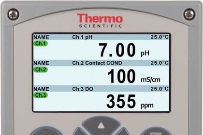
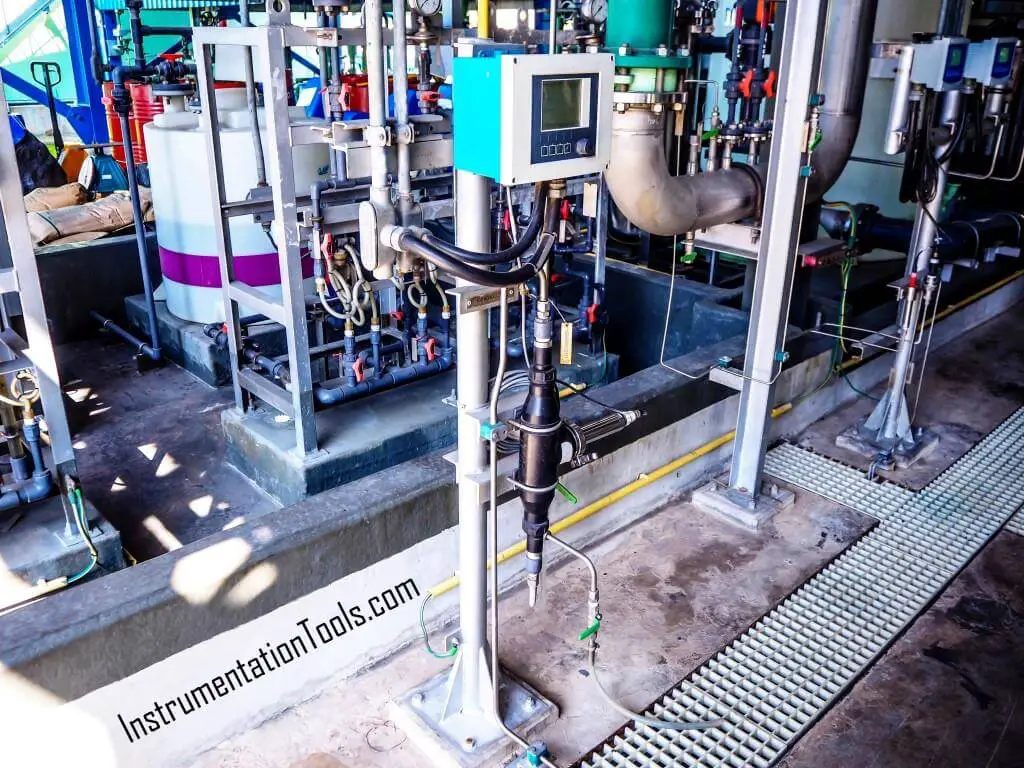
pH Analyzer
Observe these practices when calibrating the pH analyzer:
- Always rinse the probe with distilled water between calibration points.
- Never “wipe” the probe to remove excess fluid.
- Always ensure that the buffer solution inside the probe is a minimum 2/3 full.
- Keep the probe in a vertical position whenever possible.
There are two main calibration techniques:
- One-Point Calibration
- Two Point calibration
One-Point Calibration
- Ensure the temperature setting on the meter corresponds to the temperature of the buffer solutions.
- Ensure the probe is clean and rinse it with distilled water.
- Place the probe in a buffer solution of 7.00 pH.
- Adjust the zero (or equivalent) setting so the device reads 7.00.
- Rinse the probe with distilled water and return to service.
Two-Point Calibration
- Ensure the temperature setting on the meter corresponds to the temperature of the buffer solutions.
- Ensure the probe is clean and rinse it with distilled water.
- Place the probe in a buffer solution of 7.00 pH.
- Adjust the zero (or equivalent) setting so the device reads 7.00.
- Place the probe in buffer solution 4.00 pH or 10.00 pH (depending on whether the process fluid is an acid or base.)
- Adjust the gain (or equivalent) setting for 4.00 or 10.00 pH.
- Rinse the probe with distilled water and return to service.
Troubleshooting the pH Analyzer
90% of all problems with a pH measuring system are problems with the probe itself.
If there is no output signal or a maximum output signal from the transmitter, check the:
- Loop continuity.
- Loop power supply.
- The transmitter itself and follow the manufacturer’s electronic troubleshooting guide.
Cleaning and checking the probe at regular intervals (dependent on the process) is important. Depending on process conditions, the probe should be checked at regular intervals for proper levels of buffer solution.
The light coating of the probe can be cleaned by rinsing with a water jet or placing the probe under a faucet of running water, always rinse with distilled water.
Heavier coatings may require a rinse or brush with a mild acid or detergent solution. It may be necessary to soak the probe for a period of time to loosen the coating. Always rinse with distilled water.
Major coatings may require brushing or soak with a 2%-10% hydrochloric acid (HCl) solution. Always rinse with distilled water. Check for proper temperature compensation.
If the reading does not match what the pH value of the process is:
- Clean the probe as per the preceding procedure.
- The reference electrode buffer solution may be contaminated, clean the probe, replace the solution, and calibrate the system.
- The buffer solution in the measurement or reference electrode may be depleted, fill to the required level.
- The silver/silver chloride wire of the measurement probe may have been chemically attacked by the process fluid, change the probe.
- Natural aging of the measurement electrode (they have a finite life span), change the probe.
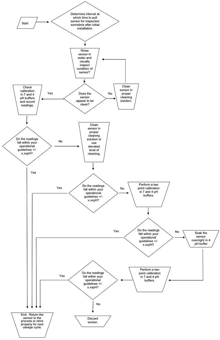
Troubleshooting Guide:
Most manufacturers approved a troubleshooting guide, follow the guide to determine the cause and solution, a typical guide is shown below.
Author: Mohammed Khaleel
Read Next:
- Level Transmitter
- Valve Stroke Test
- RTD Testing Methods
- Pressure Gauge Calibration
- HC Gas Detector Calibration