What is a Deluge Valve ?
Deluge Valves are used in conditions that require for quick application of large volumes of water and, for that reason, are often integral components in fire protection systems.
Deluge systems deliver large quantities of water, over a large area, in a relatively short period of time. They are commonly used in fixed fire protection systems whose pipe system is empty until the deluge valve distributes pressurised water from open nozzles or sprinklers.
Deluge Valve used for fast application of water in a spray system. Deluge valve protects areas such as power transformer installation, storage tank, conveyor protection and other industrial application etc. With the addition of foaming agent they do protect aircraft hanger and inflammable liquid fires also.
Also Read: Deluge Valve Transformer Protection Animation
Deluge Valve Operation
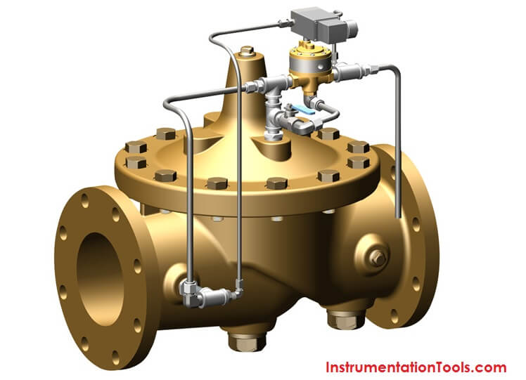
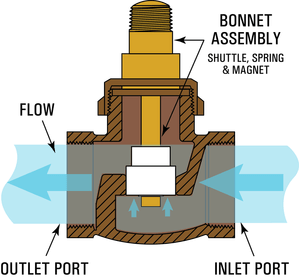
Deluge valve is a quick release, hydraulically operated diaphragm valve. It has three chambers, isolated from each other by the diaphragm operated clapper and seat seal.
While in ‘SET’ position, water pressure is transmitted through an external bypass check valve and restriction orifice from the system supply side to the top chamber , so that supply pressure in the top chamber acts across the diaphragm operated clapper which holds the seat against the inlet supply pressure because of differential pressure design.
On detection of fire the top chamber is vented to atmosphere through the outlet port via opened actuation device(s). The top chamber pressure cannot be replenished through the restricted inlet port, thus it reaches less than half the supply pressure instantaneously and the upward force of the supply pressure lifts the clapper allowing water to enter the system piping network and alarm devices
Types of Deluge Valves
a) Basic Valve
The basic trim or type is required on deluge valve regardless of the release system. It contain those components which are required in all types of installation, such as the main drain valve, priming connection, drip check valve, emergency release valve and pressure gauges.
b) DRY PILOT TRIM (PNEUMATIC RELEASE) TYPE
Dry pilot operation uses a pilot line of closed Sprinklers/QB detectors containing air under pressure, located in the area to be protected. It requires regulated dry air supply with main supply point through restricted orifice. The pilot line is connected directly to the top of POSITIVE DRAIN ACTU
ATOR (PDA). The bottom of PDA is connected to the top chamber of the deluge valve.
When the air pressure drops, due to release of any of the release devices on detection of fire, the diaphragm of PDA is lifted and allows the water to drain. This reduces the water pressure in the top chamber of the deluge valve and when the pressure in the top chamber reaches 50% of the supply pressure, the deluge valve opens.
The direct drain of PDA start when the top chamber pressure of deluge valve reaches approximately 0.5 Kg/sq.cm. This positive drain will not permit the deluge valve to close unless the PDA is set manually.
c) WET PILOT TRIM ( HYDRAULIC RELEASE) TYPE
Wet pilot operation uses a pilot line of closed sprinklers containing pressurised water , supplied through the upstream side of the deluge valve, through a restricted orifice. All the release lines are connected to a common release line.
Due to release of any one of the release devices, the water pressure in the top chamber of the deluge valve reaches 50% of the supply pressure, the deluge valve opens.
d) ELECTRIC RELEASE TRIM TYPE
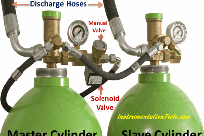
To actuate a deluge valve electrically , a solenoid valve is provided to drain the water from the top chamber of the deluge valve. A pressure switch is provided to activate an electric alarm, to shut down the desired equipment or to give “Tripped” indication to the panel.
In addition to this two nos of pressure switches can be used to monitor “Low air pressure” and “Fire condition” when used in dry pilot air line.
e) TEST AND ALARM TRIM WITH SPRINKLER ALARM TYPE
This trim is supplied with the sprinkler alarm bell, which bells on actuation of the deluge valve. A test valve is provided to test the normal operation of the sprinkler alarm bell.
Also Read: Deluge Valve Operation Types
Applications for Deluge Valves
Deluge systems are used in conditions that require quick application of large volumes of water. They create a ‘buffer zone’ in hazardous areas or in areas where fires can spread rapidly. They can also be used to cool surfaces to prevent deformation or structural collapse. Or to protect tanks, transformers, or process lines from explosion.
Other examples include: tanks containing combustible solutions; equipment pits; storage or process areas containing substances with a low flash point; or product handling systems.
Advantages and disadvantages of Deluge Valves
Advantages
- Entire Transformer is flooded with water, which extinguish fire at earliest as well as avoid further destruction.
- Very quick in response.
- The fire losses is kept low as the area near fire get cooling due to water and so chances of spreading fire is negligible.
- Less expensive than other methods
Disadvantages
- Can damage sensitive or electronic equipment
- Longer clean-up time than powder and gas systems
- Requires a large water reservoir to operation.


Useful information about the Deluge Valve.
thanks for your information about Deluge Valve, but i don’t know the use of solenoid valve for open/close deluge valve ???
Hello Alex, Solenoid Valve is used to activate the Deluge Valve from field push button or with any auto logic from DCS. (optional)
Dear sir,
Very useful for instrumentation engineers,thanks for all information
Dear Mr.reddy
How to take print out or to convert pdf of this information. Please help
Hello, You can find Print option below the articles heading. Thanks.
Dear mr reddy in automatic activation of deluge system via solenoid , why drain water is required to operate deluge valve
thanks for very useful information,now my concept clear about deluge valve
good one
GOOD
Thanks a lot ..very useful information
GOOD CLEAR IMAGINABLE PRESENTATION
GOOD THANKU
Today I specially registered on the forum to participate in the discussion of this issue.
Dear sir,
Why the valve is named Deluge? How can we relate?
can you help me out with one thing.
in auto reseting of dv the priming line connection is provided at the upstream section after the isolation valve and in non auto reseting it is postion before isolation valve.
what is the reason for it.
Dear Sir,
Can you please elaborate on the differential design to achieve valve shut during normal condition.