Inst ToolsInst ToolsInst Tools
  • Courses
  • Automation
    • PLC
    • Control System
    • Safety System
    • Communication
    • Fire & Gas System
  • Instrumentation
    • Design
    • Pressure
    • Temperature
    • Flow
    • Level
    • Vibration
    • Analyzer
    • Control Valve
    • Switch
    • Calibration
    • Erection & Commissioning
  • Interview
    • Instrumentation
    • Electrical
    • Electronics
    • Practical
  • Q&A
    • Instrumentation
    • Control System
    • Electrical
    • Electronics
    • Analog Electronics
    • Digital Electronics
    • Power Electronics
    • Microprocessor
Search
  • Books
  • Software
  • Projects
  • Process
  • Tools
  • Basics
  • Formula
  • Power Plant
  • Root Cause Analysis
  • Electrical Basics
  • Animation
  • Standards
  • 4-20 mA Course
  • Siemens PLC Course
Reading: How to Create New Project Using Simatic Manager
Share
Notification Show More
Font ResizerAa
Inst ToolsInst Tools
Font ResizerAa
  • Courses
  • Design
  • PLC
  • Interview
  • Control System
Search
  • Courses
  • Automation
    • PLC
    • Control System
    • Safety System
    • Communication
    • Fire & Gas System
  • Instrumentation
    • Design
    • Pressure
    • Temperature
    • Flow
    • Level
    • Vibration
    • Analyzer
    • Control Valve
    • Switch
    • Calibration
    • Erection & Commissioning
  • Interview
    • Instrumentation
    • Electrical
    • Electronics
    • Practical
  • Q&A
    • Instrumentation
    • Control System
    • Electrical
    • Electronics
    • Analog Electronics
    • Digital Electronics
    • Power Electronics
    • Microprocessor
Follow US
All rights reserved. Reproduction in whole or in part without written permission is prohibited.
Inst Tools > Blog > PLC Tutorials > How to Create New Project Using Simatic Manager

How to Create New Project Using Simatic Manager

Last updated: March 4, 2021 12:30 pm
Editorial Staff
PLC Tutorials
No Comments
Share
3 Min Read
SHARE

This article is about creating a new project using the Siemens Simatic manager software.

Let’s dig into the procedure of creating a new project.
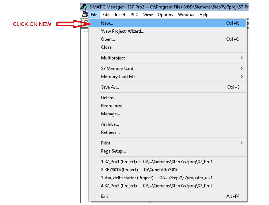
Step 1:

Open Simatic Manager. Click on “File” then click on “New”.
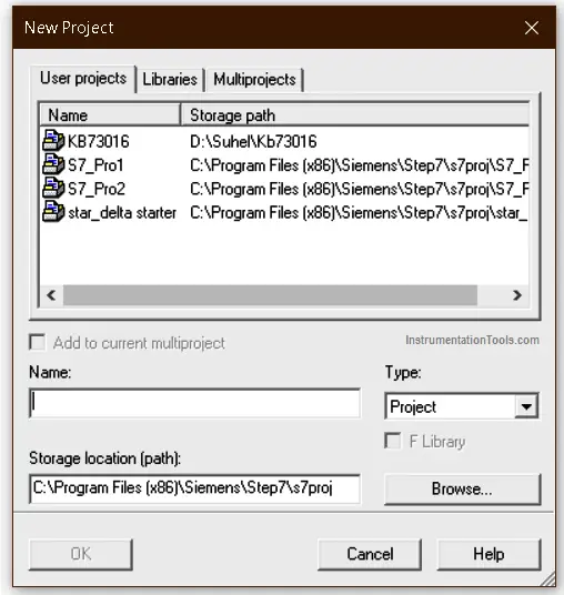
How to Create New Project Using Simatic Manager

Step 2:

Following window will pop-up. Write the name of the project and hit “ok”.
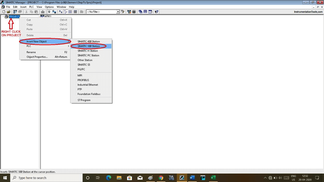
Simatic New Project

Step 3:

Right-click on “PROJECT” that is the name of the project which I have written in the last window. Go to “insert new object” and select “Simatic 300 station”.
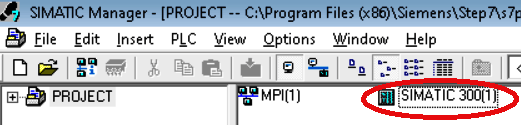
Creating a Project in Siemens Step 7

Step 4:

After adding Simatic 300 station it will add as shown in below window.
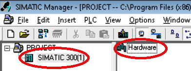
SIMATIC 300

Step 5:

As shown in the above window if you hit double click on Simatic 300 then following window will open. “Hardware” added to the project.

Simatic Hardware

Step 6:

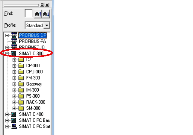
Double click on “Hardware” will pop-up new window as shown below.

SIMATIC Configuration

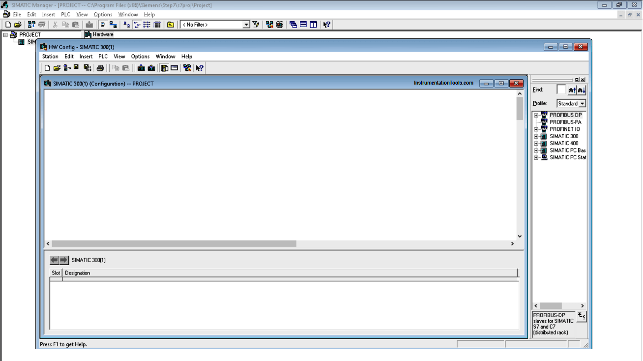
Now here, we have to select Simatic 300 station and expand it. 1st we have to add “rack”.

Step 7:

Now for Siemens PLC after adding rack(rail), in 1st slot we have to add a power supply, in 2nd slot add CPU, 3rd slot is only used for “interface module (IM)”. If you don’t have IM then leave this slot empty. In 4 to 11 slot we can add SM-signal module (input/output module).
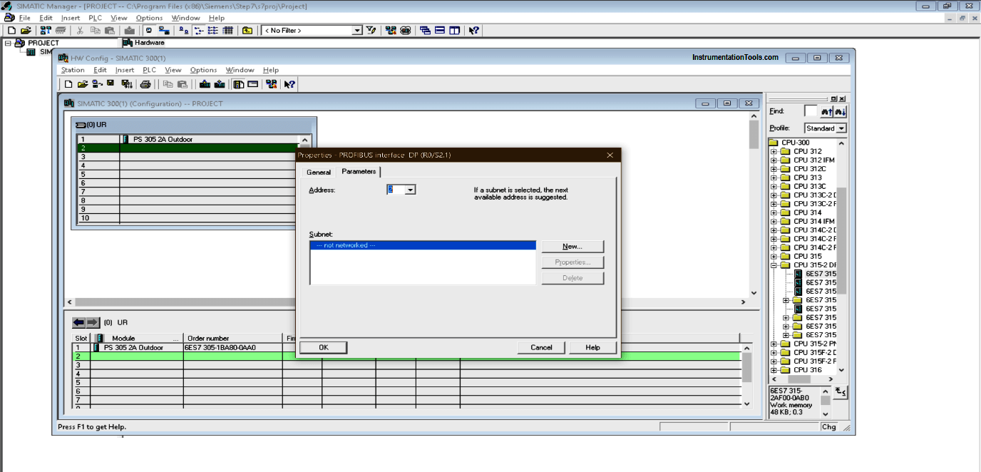
How to write a Siemens S7 300 Program

Step 8:

While adding CPU you will receive below pop-up. Here, the default address is “2”, leave as it is and hit “ok”.
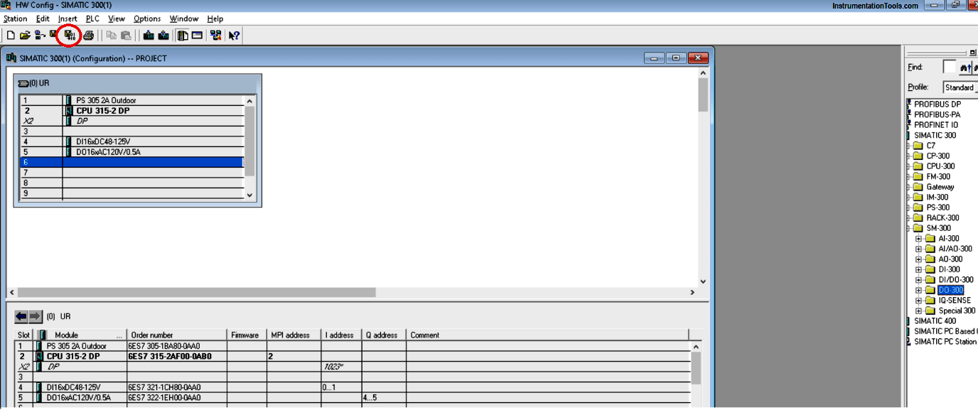
Siemens Profibus Interface DP

Step 9:

As explained in step number 7, add all the block, choose CPU and other elements as per your physical module. For the practical purpose, you can use any CPU.

After adding all element click on the icon as shown in the below window to “save and compile”.
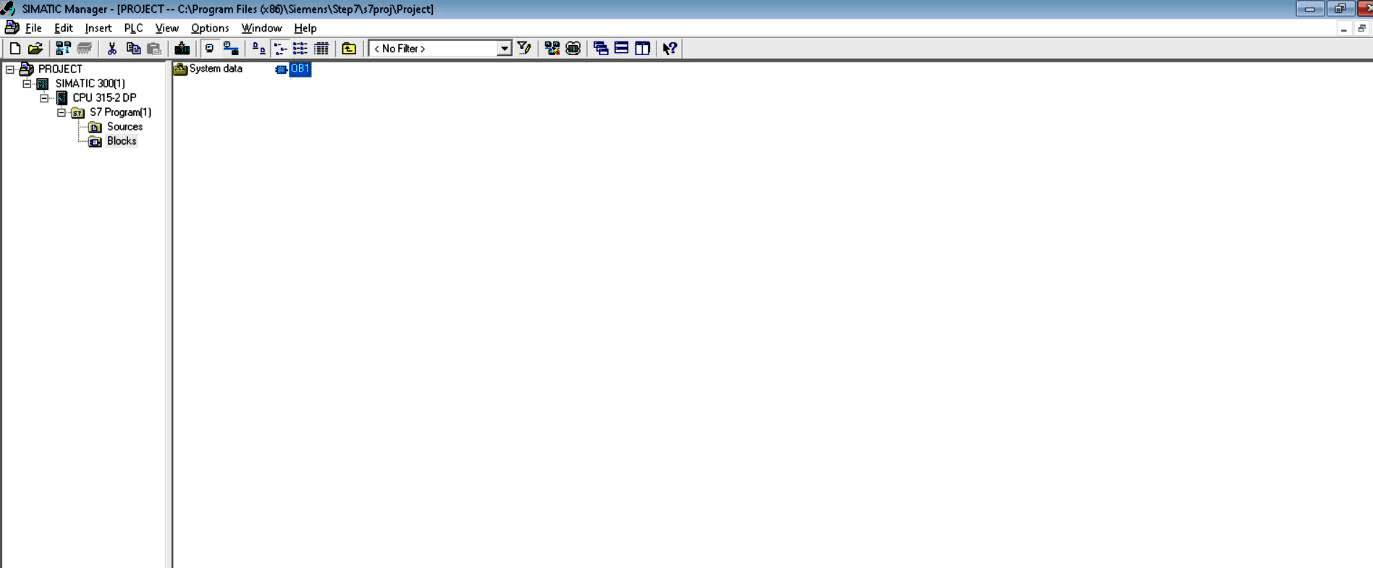
simatic manager tutorial

Step 10:

After “save and compile” project go to the main window and expand “CPU”, where you can find “block”. Select block and you can find “OB”.
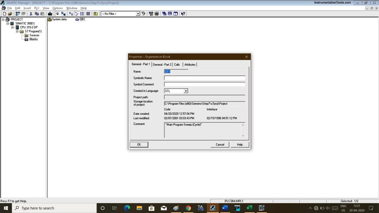
How to learn Siemens PLC

Step 11:

Clicking on “OB” will pop-up below the window. Select Ladder language and hit “ok” to enter in the programming environment.

Siemens Organization Block

Step 12:

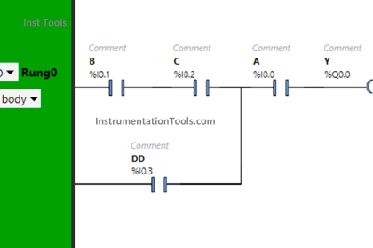
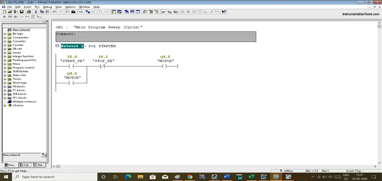
Let write a small program on DOL starter to see the programming environment and its interface.

Following is the program of the DOL starter: pressing I0.0 (PB) will set Q4.0 (MOTOR) and will remain ON despite releasing INPUT due to latching concept. Pressing I0.1(STOP_PB) will stop the Motor.

Configuration the Simatic Manager

Author: Suhel Patel

If you liked this article, then please subscribe to our YouTube Channel for PLC and SCADA video tutorials.

You can also follow us on Facebook and Twitter to receive daily updates.

Read Next:

  • Troubleshoot PLC Program
  • Protect PLC using Password
  • PLC Maths Instructions
  • JUMP Instruction in PLC
  • Siemens S7 1200 PLC
  • One-Shot Rising PLC Logic
Don't Miss Our Updates
Be the first to get exclusive content straight to your email.
We promise not to spam you. You can unsubscribe at any time.
Invalid email address
You've successfully subscribed !

Continue Reading

Why Baud Rate is Important in Modbus Network?
How to Reduce Relay Noise in PLC Systems?
How to Train Your Maintenance Team for Industrial Automation Systems?
PLC Panel and MCC Panel Interface Signals
PLC Sequential Operation Example Program
How to Update the Firmware Version of your PLC? – TIA Portal
Share This Article
Facebook Whatsapp Whatsapp LinkedIn Copy Link
Share
Leave a Comment

Leave a Reply Cancel reply

Your email address will not be published. Required fields are marked *

Stay Connected

128.3kFollowersLike
69.1kFollowersFollow
208kSubscribersSubscribe
38kFollowersFollow

Categories

Explore More

What are High-Speed Counters and Fast Counters in PLC?
InTouch SCADA Login Password Security
Types of PLC Memory
Example of Flip-Flop PLC Program for Lamps Application
DCS versus PLC Architecture
Process Interlocks and Trips
Comparison of Control Loops – Open, Closed, Cascade, Feedforward, Ratio
PLC Program for Food Processing Industry

Keep Learning

Seven Segment Display Programming with Structured Text

Seven Segment Display Programming with Structured Text

PLC Subroutine

Allen Bradley PLC Subroutines

IP Address Change in Simatic

PLC Configuration of Profinet I/O System

What is a GSD File and Why it is required?

What is a GSD File and Why it is required?

Human Machine Interface

What is Human Machine Interface (HMI) ?

PLC Multiple Choice Questions

PLC Multiple Choice Questions

Elevator PLC Ladder Logic

Elevator PLC Ladder Logic

Loop Diagram

Documentation and Change Control of PLC or DCS Systems

Learn More

Power Electronics Objective Questions

Cycloconverters Objective Questions

Gauge Cock

Pressure Gauge Cocks

Control Valves Flow Direction

Control Valve Flow Direction

Open Tank Level Measurement using DP Transmitter

Open Tank Level Measurement using DP Transmitter

Multimeter Digits

Multimeter – What Do Digits and Counts Mean?

Electrical Maintenance Engineer's Biggest Enemy

Electrical Components Overheating – Causes, Troubles, Prevent

Electric Circuits Objective Questions

Electric Circuits Objective Questions – Set 1

Thermocouple Extension Lead Minimizer Circuit

Thermocouple Wires and Extension Lead Issues

Follow US
All rights reserved. Reproduction in whole or in part without written permission is prohibited.
Welcome Back!

Sign in to your account

Username or Email Address
Password

Lost your password?