Inst ToolsInst ToolsInst Tools
  • Courses
  • Automation
    • PLC
    • Control System
    • Safety System
    • Communication
    • Fire & Gas System
  • Instrumentation
    • Design
    • Pressure
    • Temperature
    • Flow
    • Level
    • Vibration
    • Analyzer
    • Control Valve
    • Switch
    • Calibration
    • Erection & Commissioning
  • Interview
    • Instrumentation
    • Electrical
    • Electronics
    • Practical
  • Q&A
    • Instrumentation
    • Control System
    • Electrical
    • Electronics
    • Analog Electronics
    • Digital Electronics
    • Power Electronics
    • Microprocessor
  • Request
Search
  • Books
  • Software
  • Projects
  • Process
  • Tools
  • Basics
  • Formula
  • Power Plant
  • Root Cause Analysis
  • Electrical Basics
  • Animation
  • Standards
  • 4-20 mA Course
  • Siemens PLC Course
Reading: Tube Fitting Types
Share
Font ResizerAa
Inst ToolsInst Tools
Font ResizerAa
  • Courses
  • Design
  • PLC
  • Interview
  • Control System
Search
  • Courses
  • Automation
    • PLC
    • Control System
    • Safety System
    • Communication
    • Fire & Gas System
  • Instrumentation
    • Design
    • Pressure
    • Temperature
    • Flow
    • Level
    • Vibration
    • Analyzer
    • Control Valve
    • Switch
    • Calibration
    • Erection & Commissioning
  • Interview
    • Instrumentation
    • Electrical
    • Electronics
    • Practical
  • Q&A
    • Instrumentation
    • Control System
    • Electrical
    • Electronics
    • Analog Electronics
    • Digital Electronics
    • Power Electronics
    • Microprocessor
  • Request
Follow US
All rights reserved. Reproduction in whole or in part without written permission is prohibited.
Inst Tools > Blog > Erection & Commissioning > Tube Fitting Types

Tube Fitting Types

Last updated: December 22, 2018 1:09 am
Editorial Staff
Erection & Commissioning
No Comments
Share
4 Min Read
SHARE

Tube fittings designed to connect a tube to pipe threads are called connectors. Tube fittings designed to connect one tube to another are called unions:

connector and union

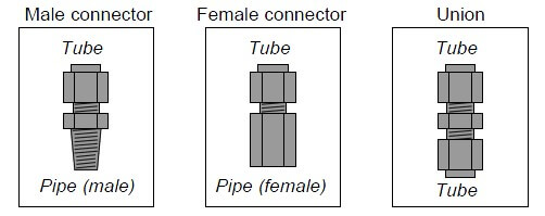
If a tube union joins together different tube sizes rather than tubes of the same size, it is called a reducing union.

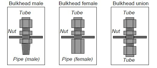
A variation on the theme of tube connectors and unions is the bulkhead fitting. Bulkhead fittings are designed to fit through holes drilled in panels or enclosures to provide a way for a fluid line to pass through the wall of the panel or enclosure. In essence, the only difference between a bulkhead fitting and a normal fitting is the additional length of the fitting and a special nut used to lock the fitting into place in the hole. The following illustration shows three types of bulkhead fittings:

Bulk head

Tubing elbows are tube connectors with a bend. These are useful for making turns in tube runs without having to bend the tubing itself. Like standard connectors, they may terminate in male pipe thread, female pipe threads, or in another tube end:

elbow

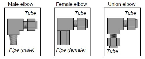
These elbows shown in the above illustration are all 90 deg, but this is not the only angle available. 45 deg elbows are also common.

Tee fittings join three fluid lines together. Tees may have one pipe end and two tube ends (branch tees and run tees), or three tube ends (union tees). The only difference between a branch tee and a run tee is the orientation of the pipe end with regard to the two tube ends:

Tee

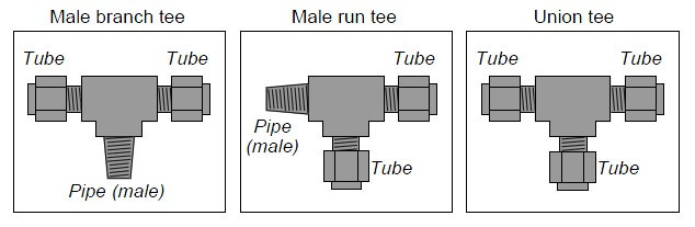
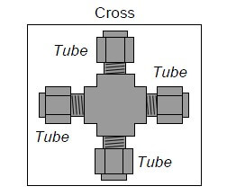
Of course, branch and run tee fittings also come in female pipe thread versions as well. A variation of the theme of union tees is the cross, joining four tubes together:

cross

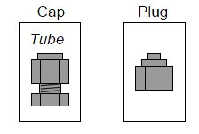
Special tube fittings are made to terminate tube connections, so they are sealed up instead of open. A piece designed to seal off the open end of a tube fitting is called a plug, while a piece designed to seal off the end of an open tube is called a cap:

cap and plug

Example:

Compression tube fittings

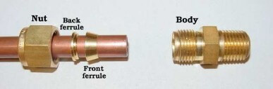
Compression fittings are used to join a section of tube to another tube, or to a thin-walled pipe, or to a piece of equipment (such as an instrument). Compression tube fitting consists of three parts: the body, the ferrule, and the nut. Some compression fitting use a two-piece ferrule assembly, such as you can see in the diagram at the below,

compressor fittings
Just prior to assembly, we see how the nut will cover the ferrule components and push them into the conical entrance of the fitting body:

Tube fittings

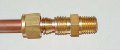
After properly tightening the nut, the ferrule(s) will compress onto the outside circumference of the tube, slightly crimping the tube in the process and thereby locking the ferrules in place:

SS Tube Connections

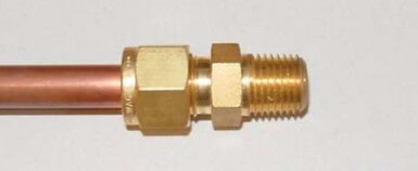
Note: a Swagelok brass instrument tube fitting being installed on a 3/8 inch copper tube.

Article Source: InstrEng

Don't Miss Our Updates
Be the first to get exclusive content straight to your email.
We promise not to spam you. You can unsubscribe at any time.
Invalid email address
You've successfully subscribed !

Continue Reading

Instrument Tube Fitting Installation – Part 1
How Not to Install an Instrument and Wrong Practices
Monsoon Protection for Field Instruments and Junction Boxes
Good and Bad Wiring Practices
How to Install Ultrasonic Level Transmitters
Basics of Ground Loops
Share This Article
Facebook Whatsapp Whatsapp LinkedIn Copy Link
Share
Leave a Comment

Leave a Reply Cancel reply

Your email address will not be published. Required fields are marked *

Stay Connected

128.3kFollowersLike
69.1kFollowersFollow
210kSubscribersSubscribe
38kFollowersFollow

Categories

Explore More

Installation and Calibration of Level Transmitter
What is Instrument Air Manifold ?
Pressure Transmitter Manifolds
Impulse Tubing Leak Test Checks
P&ID Guidelines for Pumps
Installation & Commissioning Tips for HART Devices
Commissioning a Differential Pressure Transmitter in a Pressurized Boiler Steam Drum
What is Double Block and Bleed Valves?

Keep Learning

Field Instruments enclosures

Pressure Transmitter Heated Enclosures

Magnetic Flow Meters

Magnetic Flow Meters Installation Guidelines

Common Causes of Imperfect Bends

Instrument Tube Fitting Installation – Part 3

Flow Meter Hook Up

Flow Meter Installation Guidelines

Installation Precautions of Thermocouple and RTD

Installation Precautions of Thermocouple and RTD

cable-trays-glossary

Cable Trays Glossary

Magnetic Float Level Switch Principle

Magnetic Float Level Switch Installation Techniques

P&ID arrangement for Pressure Safety Valves

P&ID Guidelines for Pressure Safety Valves

Learn More

Renewable Energy Projects

200 Renewable Energy Projects for Students and Engineers

Sensor Based Projects List - Electronics & Electrical

350+ Sensor-Based Projects List – Electronics & Electrical

Definitions of Electrical Grounding

Definitions of Electrical Grounding

ECE Projects - IEEE and IoT Projects List

ECE Projects – IEEE and IoT Projects List

Voltage Polarities

Voltage Polarity and Current Direction

Induction Motor Interview Questions & Answers

Induction Motor Interview Questions & Answers

Important Networking Interview Questions

Important Networking Interview Questions

Power Electronics Objective Questions

Thyristors Quiz

Menu

  • About
  • Privacy Policy
  • Copyright

Quick Links

  • Learn PLC
  • Helping Hand
  • Part Time Job

YouTube Subscribe

Follow US
All rights reserved. Reproduction in whole or in part without written permission is prohibited.
Welcome Back!

Sign in to your account

Username or Email Address
Password

Lost your password?