Inst ToolsInst ToolsInst Tools
  • Courses
  • Automation
    • PLC
    • Control System
    • Safety System
    • Communication
    • Fire & Gas System
  • Instrumentation
    • Design
    • Pressure
    • Temperature
    • Flow
    • Level
    • Vibration
    • Analyzer
    • Control Valve
    • Switch
    • Calibration
    • Erection & Commissioning
  • Interview
    • Instrumentation
    • Electrical
    • Electronics
    • Practical
  • Q&A
    • Instrumentation
    • Control System
    • Electrical
    • Electronics
    • Analog Electronics
    • Digital Electronics
    • Power Electronics
    • Microprocessor
  • Request
Search
  • Books
  • Software
  • Projects
  • Process
  • Tools
  • Basics
  • Formula
  • Power Plant
  • Root Cause Analysis
  • Electrical Basics
  • Animation
  • Standards
  • 4-20 mA Course
  • Siemens PLC Course
Reading: Questions on Chemical Reactor Vessel P & ID
Share
Font ResizerAa
Inst ToolsInst Tools
Font ResizerAa
  • Courses
  • Design
  • PLC
  • Interview
  • Control System
Search
  • Courses
  • Automation
    • PLC
    • Control System
    • Safety System
    • Communication
    • Fire & Gas System
  • Instrumentation
    • Design
    • Pressure
    • Temperature
    • Flow
    • Level
    • Vibration
    • Analyzer
    • Control Valve
    • Switch
    • Calibration
    • Erection & Commissioning
  • Interview
    • Instrumentation
    • Electrical
    • Electronics
    • Practical
  • Q&A
    • Instrumentation
    • Control System
    • Electrical
    • Electronics
    • Analog Electronics
    • Digital Electronics
    • Power Electronics
    • Microprocessor
  • Request
Follow US
All rights reserved. Reproduction in whole or in part without written permission is prohibited.
Inst Tools > Blog > Common > Questions on Chemical Reactor Vessel P & ID

Questions on Chemical Reactor Vessel P & ID

Last updated: January 27, 2020 9:42 am
Editorial Staff
Common
4 Comments
Share
2 Min Read
SHARE

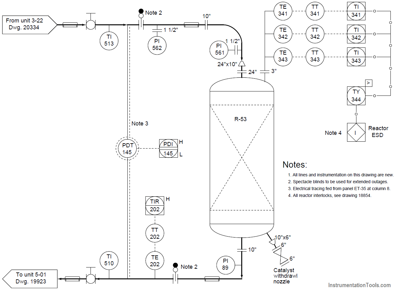
Examine this portion of a P&ID. This particular diagram shows some of the piping and instrumentation associated with a chemical reactor vessel:

Chemical Reactor Vessel P & ID

Chemical Reactor Vessel P and ID

Question 1:

Which direction does process fluid flow through this reactor vessel? How can we tell from the diagram?

Question 2:

Identify the functions of all instrument “bubbles” shown in this diagram, as well as the meanings of their identifying tag letters (e.g. “PDT”).

Question 3:

How are piping flanges shown in a PFD or P&ID?

Question 4:

What is the meaning of the trapezoidal symbols with two sizes (e.g. 10” × 24”)?

Question 5:

Two places on this diagram show the placement of a blind, used to positively seal off a pipe at a flange for maintenance purposes. Locate these two blind installations in the diagram.

Note: If a blind or another other safety device needs to be left in its safe state for any specific reason, the person engaging that safety device must lock it in place and tag it with an informative tag stating the reason and duration of the lock-out. This is commonly referred to as a lock-out, tag-out procedure.

Question 6:

Some of the indicators shown in this P&ID serve double-duty as process alarms. Identify which of the indicators also have alarm functions, and which of those are high alarms, low alarms, or both.

Question 7:

Based on what you see in this P&ID, what do you think the purpose of PDT-145 is?

Question 8:

Based on what you see in this P&ID, what do you think is the purpose of having three temperature transmitters at the top of the vessel?

Share Your Answers with us through comments.

Credits: Tony R. Kuphaldt

Read Next:

  • Instrument Hook Up Diagram
  • Instrument Loop Diagram
  • What is Block Diagram
  • Control Loop Wiring 
  • Process Variables in P&ID
Don't Miss Our Updates
Be the first to get exclusive content straight to your email.
We promise not to spam you. You can unsubscribe at any time.
Invalid email address
You've successfully subscribed !

Continue Reading

Pharmaceutical Industry: The Role of Precision Tools
The Impact of Knowledge Management Platforms on Business Operations
Digital Measuring Instruments – Types, Functions, Advantages, Disadvantages
What is SOP and How to Create an SOP?
What is an Automotive Radiator?
How ANSI Class Relates to PSI ?
Share This Article
Facebook Whatsapp Whatsapp LinkedIn Copy Link
Share
4 Comments
  • jitendra meena says:
    January 22, 2020 at 8:22 pm

    Ans.1

    process fluid flows from top of the vessels to bottom of the vessels or from unit 3-22 to unit 5-01.
    process fluid flow is indicates by arrow sign at the top and bottom of the vessels.

    Ans 2.

    TI : TEMPERATURE INDICATOR
    TE: TEMPERATURE ELEMNT
    PDT: DIFFERENTIAL PRESSURE TRANSMITTER

    Reply
  • ELUDU DAVID says:
    January 24, 2020 at 9:02 am

    1. from the top of the reactor
    2. PDT means Differential pressure transmitter
    3. with a vertical line
    4. Enlarger
    5.
    6. TIR-202 High alarm and PDI-145 high and low alarms
    7. PDI-145 is to check the differential between the inlet and outlet pressure
    8. To effectively monitor the temperatures on the reactor. Paraventures one of the transmitters fails, the other two serves as reference.

    Reply
  • Sonny says:
    January 24, 2020 at 10:12 am

    Answer 8: as it is a critical process control, so requires 2oo3 voting logic connected to ESD. You need minimum 2 transmitters to detect the process temperature to make a trip of the respectie logic/plant section

    Reply
  • Ahmed seif says:
    February 2, 2021 at 3:48 am

    Ans 1
    Process lines heavier than instrument lines
    Input from top of vessel from unit 3-22
    Arrows direction also appear process flow direction

    Ans 2
    TI temperture indicator
    PI pressure indicator
    TE Temperature element
    TT Temperature transmitter
    TIR Temperature indicator recorder
    PDT pressure differential transmitter
    PDI pressure differential indicator
    TY Temperature high select

    Ans 3
    With verticale line
    ANSI/ISA symbol


    Ans 4

    Expander which enlarge the pipe from 10 inch to 24 inch

    Ans 5
    At note 2 hahhaha

    Ans 6
    PDIHL
    TIRH

    Ans7
    PDT – 145 measue differential pressure between input and output of vessel lines
    If Dp greater than certain value it will give alarm for clogged in vessel
    If DP less than certain value mean that vessel not work efficiently

    Ans 8
    Firstly send three reading to DCS
    Insure reading because they are measure same point
    Make voting in case of one transmiter failure thats will make system not stopped in case of one transmitter failure
    Also make interlock for system in case of temperture of greater sensor value more than certain value
    Also indicate Temperature on DCS
    Also used for SIS system safty instrument system

    Reply

Leave a Reply Cancel reply

Your email address will not be published. Required fields are marked *

Stay Connected

128.3kFollowersLike
69.1kFollowersFollow
210kSubscribersSubscribe
38kFollowersFollow

Categories

Explore More

Types of Sensors used in the Dairy Industry
Why is Instrumentation used in Industries?
Lag time
Advancements in Lime Slaking Technology: What’s New And What’s Next
IPv4 vs IPv6 – What’s the Difference Between IP addresses?
What is a Database Server? – Types, Comparison
Sugar Plant – Automatic Control of Massecuite Feed
What is the Address Resolution Protocol? – Types of ARP

Keep Learning

What is a Voltage Reference

What is a Voltage Reference? – Electronic Components

Password Protect Apps and Files

5 Best Mobile Apps to Password Protect Applications and Files

Sugar Industry Logics

Mill Interlocks in the Sugar Industry

Field Instrumentation Tips

Field Instrumentation Tips

Roller Conveyor

Difference Between Belt Conveyor and Roller Conveyor

Understanding RS-485 Communication

Understanding RS-485 Communication

How are Data Centers Cooled

How are Data Centers Cooled?

Meters used in Troubleshooting Electrical Equipment

Meters used in Troubleshooting Electrical Equipment

Learn More

different flow measurement technologies

Different Flow Measurement Technologies

Lime Slaker

Advancements in Lime Slaking Technology: What’s New And What’s Next

Top 100 PLC Objective Questions and Answers

Top 100 PLC Objective Questions and Answers

Types of Resistors

Types of Resistors

Glass Cutting and Polishing Machine PLC Automation Solution

Glass Cutting and Polishing Machine: PLC Automation Solution

Insulators, Conductors and Semiconductors

RF-Capacitance Level Switch Principle

RF Capacitance Level Switch Working Principle

NH3 Plant Turbo-compressor Sudden Rise in Temperature

NH3 Plant Turbo-compressor Sudden Rise in Temperature

Menu

  • About
  • Privacy Policy
  • Copyright

Quick Links

  • Learn PLC
  • Helping Hand
  • Part Time Job

YouTube Subscribe

Follow US
All rights reserved. Reproduction in whole or in part without written permission is prohibited.
Welcome Back!

Sign in to your account

Username or Email Address
Password

Lost your password?