Inst ToolsInst ToolsInst Tools
  • Courses
  • Videos
  • Q & A
    • Interview
      • Instrumentation
      • Electronics
      • Electrical
      • Practical Questions
    • MCQ
      • Instrumentation MCQ
      • Electrical MCQ
      • Electronics MCQ
      • Control Systems MCQ
      • Analog Electronics MCQ
      • Digital Electronics MCQ
      • Power Electronics MCQ
      • Microprocessor MCQ
      • Multiple Choice Questions
  • EE
    • Electronics
      • Electronics Q & A
      • Electronic Basics
      • Electronic Devices & Circuits
      • Electronics Animation
      • Digital Electronics
    • Electrical
      • Electrical Basics
      • Electrical Q & A
      • Power Electronics
      • Electrical Machines
      • Electrical Animation
      • Power Systems
      • Switchgear & Protection
      • Transmission & Distribution
  • Measure
    • Control Valves
    • Calibration
    • Temperature
    • Pressure
    • Flow
    • Level
    • Analyzers
    • Switches
    • Vibration
    • Solenoid Valve
  • Control
    • PLC Tutorials
    • Control Systems
    • Safety Instrumented System (SIS)
    • Communication
    • Fire & Gas System
  • More
    • Design
    • Tools
    • Animation
    • Basics
    • Formulas
    • Standards
    • TextBooks
    • Common
    • Software
    • Excel Tools
    • Erection & Commissioning
    • Process Fundamentals
    • Videos
    • Books
Search
All rights reserved. Reproduction in whole or in part without written permission is prohibited.
Reading: Create a Function (FC) for a Valve Logic in Siemens PLC
Share
Notification Show More
Font ResizerAa
Inst ToolsInst Tools
Font ResizerAa
  • Courses
  • PLC Tutorials
  • Control Systems
Search
  • Courses
  • Videos
  • Q & A
    • Interview
    • MCQ
  • EE
    • Electronics
    • Electrical
  • Measure
    • Control Valves
    • Calibration
    • Temperature
    • Pressure
    • Flow
    • Level
    • Analyzers
    • Switches
    • Vibration
    • Solenoid Valve
  • Control
    • PLC Tutorials
    • Control Systems
    • Safety Instrumented System (SIS)
    • Communication
    • Fire & Gas System
  • More
    • Design
    • Tools
    • Animation
    • Basics
    • Formulas
    • Standards
    • TextBooks
    • Common
    • Software
    • Excel Tools
    • Erection & Commissioning
    • Process Fundamentals
    • Videos
    • Books
Follow US
All rights reserved. Reproduction in whole or in part without written permission is prohibited.
Inst Tools > Blog > PLC Tutorials > Create a Function (FC) for a Valve Logic in Siemens PLC

Create a Function (FC) for a Valve Logic in Siemens PLC

Last updated: March 4, 2021 2:43 pm
Editorial Staff
PLC Tutorials
No Comments
Share
5 Min Read
SHARE

Let us study how to create a Function Block (FC) for a Valve Control Logic in PLC. This article focuses on Siemens function block programming for the control valve with example.

Contents
Valve LogicList of Inputs:-List of Outputs:-Create a Function (FC) in Siemens PLCFC BlockNetwork 1:-Network 2:-Network 3:-

Valve Logic

There are two valve functions in this application. Valve opening and closing can be controlled by giving OPEN and CLOSE commands. So Consider two outputs for valve open command and valve close command.

Valve Control Logic

When we need to write a logic for many valves in a plant then we use the FC blocks. So here we will write the logic for the valve by using the FC block.

For example, we have one valve to control it manually from PLC. So we need two buttons in the graphics for controlling the valve position, i.e. for valve opening and valve closing.

An operator will press the valve open button for the valve opening position. Similarly, the operator press the valve close button for the valve closing position.

Valve has the two proximity switches installed on it to know the valve position. So, two feedback signals will be generated for the open position and also for the close position. So PLC will receive these feedback signals and display the valve status on the graphics.

In this example, we will take FC block and write the logic for the valve. Declare all temporary variables in the table.

After configuration of FC, take OB 1 and call FC in OB 1. You Call this FC block many times in the logic. Use the FC block for each time when you want to implement the control logic for the valves.

For example, we will consider one valve control logic.
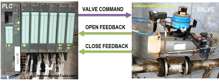
PLC Valve Control Example

List of Inputs:-

  • I0.0:- valve Open
  • I0.1:- Valve close

List of Outputs:-

  • Q0.0:- Valve ON
  • Q0.1:- Valve Open Command
  • Q0.2:- Valve Close Command

Create a Function (FC) in Siemens PLC

OB1:- Organization block for valve control logic. FC 1 is called in OB 1. As shown in the below figure we can drag FC 1 in OB 1 for valve control logic.
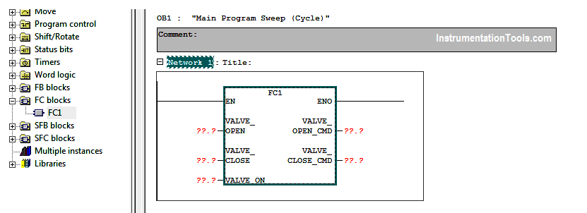
Create a Function (FC) Siemens PLC

FC Block

We have called FC 1 only for one valve in the OB1. Generally, FC can be called multiple times. If there are more valves in the application, FC 1 can be called for another valve also, no need to write logic every time.

For FC, no need to create separate DB like FB configuration. Here when we press the valve open (I0.0), the valve (Q0.0) will be ON and if the valve close (I0.1) is pressed, the valve will be closed.
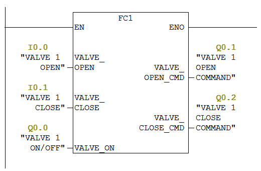
Control Valve Function in PLC

FC 1:- In Simatic manager, we can configure FC or another block by clicking on insert new object.

Add Function in the program as shown in the below figure.
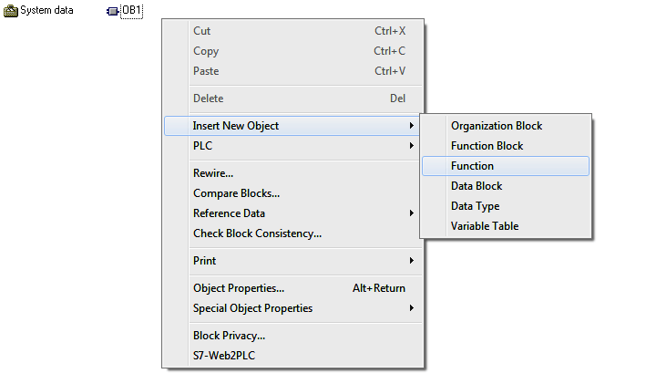
Configure FC block in Simatic Manager

After FC configuration, declare all temporary variables in the table as shown in the below figure.

FC configuration in PLC

Network 1:-

In this network, we have taken a temporary variable for valve ON/OFF. By pressing the valve open, valve can be opened and by pressing the close button, valve can be closed.
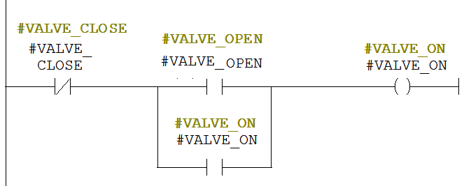
Valve Open Ladder Logic

Network 2:-

If the valve (Q0.0) is ON, Valve open command (Q0.1) should be ON.

Valve Open Command in PLC

Network 3:-

If the valve (Q0.0) is ON, valve close command (Q0.2) should be ON.

Valve Close Command in PLC

As per the above explanation, you can write the logic for other valves also. Call FC in OB 1 for the second valve and configure the inputs and outputs.

Note:- This is the simple example for the FC block used for valve application in PLC, we can use this concept in other examples also.

Author: Bhavesh

If you liked this article, then please subscribe to our YouTube Channel for PLC and SCADA video tutorials.

You can also follow us on Facebook and Twitter to receive daily updates.

Read Next:
Control Valve Ladder Logic

PLC Tank Filling Logic

Proximity Switch Principle

Solenoid Valve Working

Motor Control using PLC

Don't Miss Our Updates
Be the first to get exclusive content straight to your email.
We promise not to spam you. You can unsubscribe at any time.
Invalid email address
You've successfully subscribed !

Continue Reading

T-Junction Traffic Control System – PLC Programming
Automatic Coffee Vending Machine – PLC Logic Programming
How to Password Protect HMI in Siemens TIA Portal?
Why Use Normally-Closed Contact for Stop Buttons?
AENT Module in Rockwell PLC – Remote IO Adapter
Advanced Skills Required for a PLC Programmer to Get a Job
Share This Article
Facebook Whatsapp Whatsapp LinkedIn Copy Link
Share
Leave a Comment

Leave a Reply Cancel reply

Your email address will not be published. Required fields are marked *

Stay Connected

128.3kFollowersLike
69.1kFollowersFollow
208kSubscribersSubscribe
38kFollowersFollow

Categories

Explore More

PLC Question Bank
PLC Power Supply and Operating Voltages
Sheets, Tags, Elements in Functional Block Diagram of Studio 5000
LS Electric PLC Program Example: Clothes Washing System
How to Solve Electrical Ground Loop Problems?
PLC Output Types
Troubleshooting a 4-20mA Current loop
What is a Retro-Reflective Sensor? – Principle, Applications
Basics of 4 to 20 mA analog Signals
What is a PLC Retrofitting Project? – Importance, Procedure

Keep Learning

Key Facts About RS485 Industrial Network

Key Facts About RS485 Industrial Network

VFD Pros and Cons - Variable Frequency Drives

VFD Pros and Cons – Variable Frequency Drives

Most Asked Questions on SCADA

Most Asked Questions on SCADA with Answers

Grounding Electronic Equipment

Importance of Grounding Electronic Equipment

PLC Motor Logic

Interconnection between PLC, MCC, LCP & Pumps – Video

Omron PLC painting program

Product Painting PLC Program using Omron CX-Programmer

How to Control VFD with PLC using Ladder Logic

Check Block Consistency Tools

Check Block Consistency Tools in Simatic Manager

Discover More

Top 100 Proteus Design Suite Projects for Engineering Students

Top 100 Proteus Design Suite Projects for Engineering Students

Cables Sheath Material

Instrument Cables Sheath Material

Thermocouple Calculations

Free Download Thermocouple Calculator

Light Tower in Industrial Automation

What is a Tower Lamp? – Light Tower in Industrial Automation

Turbine Supervisory Instrumentation

What is Turbine Supervisory Instrumentation (TSI)?

H & B Gas Analyzer Principle and Calibration Procedure

Root Locus Concepts Objective Questions

Construction of Root Loci

TON Timer in RSlogix

Why is RTO used in the Place of TON Timer?

Follow US
All rights reserved. Reproduction in whole or in part without written permission is prohibited.
Welcome Back!

Sign in to your account

Username or Email Address
Password

Lost your password?