Inst ToolsInst ToolsInst Tools
  • Courses
  • Automation
    • PLC
    • Control System
    • Safety System
    • Communication
    • Fire & Gas System
  • Instrumentation
    • Design
    • Pressure
    • Temperature
    • Flow
    • Level
    • Vibration
    • Analyzer
    • Control Valve
    • Switch
    • Calibration
    • Erection & Commissioning
  • Interview
    • Instrumentation
    • Electrical
    • Electronics
    • Practical
  • Q&A
    • Instrumentation
    • Control System
    • Electrical
    • Electronics
    • Analog Electronics
    • Digital Electronics
    • Power Electronics
    • Microprocessor
  • Request
Search
  • Books
  • Software
  • Projects
  • Process
  • Tools
  • Basics
  • Formula
  • Power Plant
  • Root Cause Analysis
  • Electrical Basics
  • Animation
  • Standards
  • 4-20 mA Course
  • Siemens PLC Course
Reading: Allen Bradley Math Functions
Share
Font ResizerAa
Inst ToolsInst Tools
Font ResizerAa
  • Courses
  • Design
  • PLC
  • Interview
  • Control System
Search
  • Courses
  • Automation
    • PLC
    • Control System
    • Safety System
    • Communication
    • Fire & Gas System
  • Instrumentation
    • Design
    • Pressure
    • Temperature
    • Flow
    • Level
    • Vibration
    • Analyzer
    • Control Valve
    • Switch
    • Calibration
    • Erection & Commissioning
  • Interview
    • Instrumentation
    • Electrical
    • Electronics
    • Practical
  • Q&A
    • Instrumentation
    • Control System
    • Electrical
    • Electronics
    • Analog Electronics
    • Digital Electronics
    • Power Electronics
    • Microprocessor
  • Request
Follow US
All rights reserved. Reproduction in whole or in part without written permission is prohibited.
Inst Tools > Blog > PLC Tutorials > Allen Bradley Math Functions

Allen Bradley Math Functions

Last updated: March 4, 2021 3:23 pm
Editorial Staff
PLC Tutorials
No Comments
Share
5 Min Read
SHARE

To study the working of Allen Bradley Math functions (ADD, SUB, MUL, DIV, SQR & NEG) using simple example in programmable logical controllers (PLC).

Contents
Allen Bradley Math FunctionsPLC Math FunctionsADD:SUB:MUL:DIV:SQRNEQ:Program LogicPLC Program using Math FunctionsLadder Logic Description:Conclusion:

Allen Bradley Math Functions

Working with Math Blocks in AB PLC

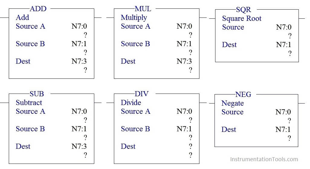
There are three parameters in each block,

Source A –Address of the first Value

 Source B –Address of the second value

Destination (Dest) – Address where result of the function will store.

PLC Math Functions

ADD:

Add block is used to do the Addition of the two values stored in source A and source B and store the output in  destination address.

SUB:

Sub block is used to do the Subtraction of the two values stored in source A and source B and store the output in destination address.

MUL:

MUL block is used to do the Multiplication of the two values stored in source A and source B and store the output in destination address.

DIV:

DIV block is used to do the Division of the two values stored in source A and source B and store the output in destination address.

SQR

SQR block is used to find the square root of the value stored in source address and results the value in destination address.

NEQ:

NEQ block is used to negate the value stored in source address and results the value in destination.

Program Logic

When start switch is pressed,

  1. Value stored in N7:0 and N7:1 gets added and results the value in N7:2
  2. Add block output is one of the input to Sub block which do subtraction function by taking value stored in N7:1 and stores the address in N7:3.
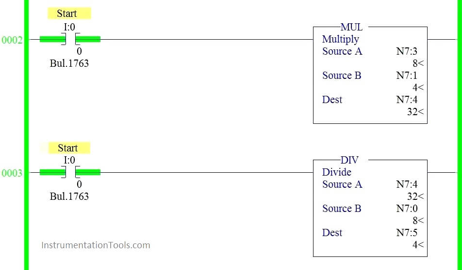
  3. Sub block output is one the input to Mul block and perform multiplication along with value stored in N7:1 and stores the result in N7:4
  4. Mul block output is one the input to DIV block and perform Division along with value stored in N7:0 and stores the result in N7:5
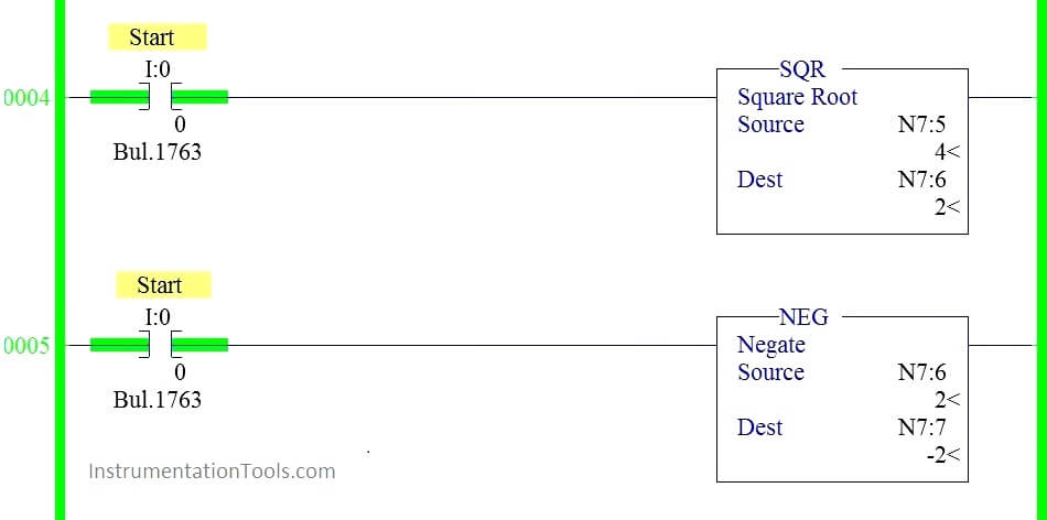
  5. SQR block performs square root of the Value stored in N7:5 and results the output in N7:6.
  6. Value stored in N7:6 get negated using NEG block and results the final output in N7:7.
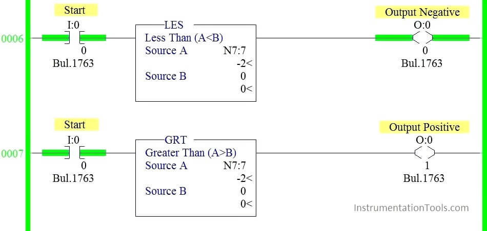
  7. If the resulted output is positive turn on output positive indication else output negative indication.

PLC Program using Math Functions
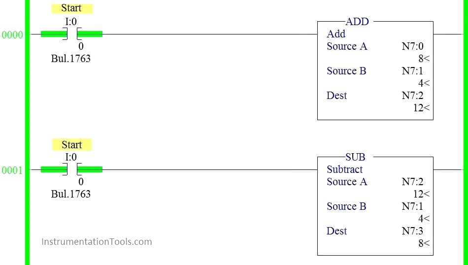
ADD and SUB Blocks in PLC Programming
MUL and DIV Blocks in PLC Programming
SQR and NEG Blocks in PLC Programming
LES and GRT Blocks in PLC Programming

Ladder Logic Description:

RUNG 0000:

When Start switch is pressed, N7:0 and N7:1 get added and store the value in N7:2.

RUNG 0001:

Value stored in N7:2 get subtracted with value stored in N7:1 and results the value in N7:3.

RUNG 0002:

Value stored in N7:3 get multiplied with value stored in N7:1 and results the value in N7:4.

RUNG 0003:

Value stored in N7:4 get divided by value stored in N7:0 and results the value in N7:5.

RUNG 0004:

Value stored in N7:5 get squared and results the value in N7:6.

RUNG 0005:

Value stored in N7:6 get negated and results the value in N7:7.

RUNG 0006:

Less than block (Source B value sets to 0) is used to check whether the result is negative and results the output in indication lamp (O: 0/0)

RUNG 0007:

Greater than block (Source B value sets to 0) is used to check whether the result is positive and results the output in indication lamp (O: 0/1)

Conclusion:

We can use this example program to understand the working Math block functions in AB PLC.

Author : Hema Sundaresan

If you liked this article, then please subscribe to our YouTube Channel for PLC and SCADA video tutorials.

You can also follow us on Facebook and Twitter to receive daily updates.

Read Next:

Single Push button Ladder Logic

Motor Logic with Push buttons

What is Latching in PLC ?

Masked Move Instruction in PLC
What is Interlocking in PLC ?

Don't Miss Our Updates
Be the first to get exclusive content straight to your email.
We promise not to spam you. You can unsubscribe at any time.
Invalid email address
You've successfully subscribed !

Continue Reading

PLC Program for Sequential Motor Control
Peripheral Inputs and Outputs in Siemens PLC
#12 PLC Best Practices – Validate Inputs based on Physical Plausibility
PLC Logic for Automatic Bending Machine for Exhaust Pipe
Communication between Factory IO and Siemens Tia Portal
Components of SCADA
Share This Article
Facebook Whatsapp Whatsapp LinkedIn Copy Link
Share
Leave a Comment

Leave a Reply Cancel reply

Your email address will not be published. Required fields are marked *

Stay Connected

128.3kFollowersLike
69.1kFollowersFollow
210kSubscribersSubscribe
38kFollowersFollow

Categories

Explore More

Understanding the Scan Cycle of SIEMENS PLC
PLC Multiple Choice Questions
Medium-Level PLC Exercise for Students in Automation
PLC Program for Automatic Mixing Control in a Tank
#13 PLC Best Practices – Disable Unused Communication Ports
How to Filter Digital and Analog Inputs in a PLC?
Sink or Source? Normally Open or Normally Closed?
PLC Automatic Pedal Switch for Speed Control

Keep Learning

Grounding Electronic Equipment

Importance of Grounding Electronic Equipment

PLC Program with 2 Toggle Switches and 4 Motors

PLC Program with 2 Toggle Switches and 4 Motors

Failsafe interlock Design

Failsafe Wiring Practices

PLC Programming Best Practices and Tips

PLC Programming Best Practices and Tips

PLC Motor Logic with START, STOP, TEST Push buttons

PLC Motor Logic with START, STOP, TEST Push buttons

Turbine-Compressor System Architecture

Turbine-Compressor System Architecture

Online PLC Ladder Logic

Mis-conceptions of PLC Ladder Logic

Basics of Loop Checks

Basics of Loop Checks

Learn More

CEMS Classification

CEMS Principle, Types, Advantages, and Disadvantages

VFD Block Diagram

What is a VFD? – Theory, Advantages, Disadvantages

Control Systems Questions & Answers

Control Systems Objective Questions & Answers – Set 5

Top Non-PLC Certification Courses for Automation Professionals

Top Non-PLC Certification Courses for Automation Professionals

MTech Project Ideas for Electronics and Electrical Engineering

100 MTech Project Ideas for Electronics and Electrical Engineering

Analyzers Questions and Answers

Electrochemical Methods for Oxygen Analysis Questions & Answers

Capping Machines

Capping Machine – 5 Aspects of Control Systems and Automation

Digital Control Systems

The inverse z-transform & Response of Linear Discrete Systems

Menu

  • About
  • Privacy Policy
  • Copyright

Quick Links

  • Learn PLC
  • Helping Hand
  • Part Time Job

YouTube Subscribe

Follow US
All rights reserved. Reproduction in whole or in part without written permission is prohibited.
Welcome Back!

Sign in to your account

Username or Email Address
Password

Lost your password?