Inst ToolsInst ToolsInst Tools
  • Courses
  • Automation
    • PLC
    • Control System
    • Safety System
    • Communication
    • Fire & Gas System
  • Instrumentation
    • Design
    • Pressure
    • Temperature
    • Flow
    • Level
    • Vibration
    • Analyzer
    • Control Valve
    • Switch
    • Calibration
    • Erection & Commissioning
  • Interview
    • Instrumentation
    • Electrical
    • Electronics
    • Practical
  • Q&A
    • Instrumentation
    • Control System
    • Electrical
    • Electronics
    • Analog Electronics
    • Digital Electronics
    • Power Electronics
    • Microprocessor
Search
  • Books
  • Software
  • Projects
  • Process
  • Tools
  • Basics
  • Formula
  • Power Plant
  • Root Cause Analysis
  • Electrical Basics
  • Animation
  • Standards
  • 4-20 mA Course
  • Siemens PLC Course
Reading: PLC Ladder Logic for Tanks Filling as per Priority
Share
Notification Show More
Font ResizerAa
Inst ToolsInst Tools
Font ResizerAa
  • Courses
  • Design
  • PLC
  • Interview
  • Control System
Search
  • Courses
  • Automation
    • PLC
    • Control System
    • Safety System
    • Communication
    • Fire & Gas System
  • Instrumentation
    • Design
    • Pressure
    • Temperature
    • Flow
    • Level
    • Vibration
    • Analyzer
    • Control Valve
    • Switch
    • Calibration
    • Erection & Commissioning
  • Interview
    • Instrumentation
    • Electrical
    • Electronics
    • Practical
  • Q&A
    • Instrumentation
    • Control System
    • Electrical
    • Electronics
    • Analog Electronics
    • Digital Electronics
    • Power Electronics
    • Microprocessor
Follow US
All rights reserved. Reproduction in whole or in part without written permission is prohibited.
Inst Tools > Blog > PLC Tutorials > PLC Ladder Logic for Tanks Filling as per Priority

PLC Ladder Logic for Tanks Filling as per Priority

Last updated: March 4, 2021 3:29 pm
Editorial Staff
PLC Tutorials
1 Comment
Share
3 Min Read
SHARE

Write the PLC program for two tanks filling as per priority. Design the PLC Ladder Logic programming for this application.

Contents
Tanks Filling as per PriorityPLC I/OPLC Programming

Tanks Filling as per Priority

Two Tanks Filling using PLC

In pneumatic conveying system two or more tanks are used for material supply. Sometimes it is necessary to define priority for tanks. For example, if there are two feeding tanks are used in system and both the tanks are empty so we which tank should be filled first?

So write priority logic in PLC for this problem. In this example we have taken two feeding tanks and we will fill tank as per priority. Hence we will fill tank 1 first if booth the tanks are detected empty.

PLC I/O

List of Inputs

  • I1 :- Start PB
  • I2 :- Stop PB
  • I3 :- Tank 1 low level sensor (LL)
  • I4 :- Tank 1 high level sensor (HL)
  • I5 :- Tank 2 low level sensor (LL)
  • I6 :- Tank 2 high level sensor (HL)

List of Outputs

  • Q1 :- Cycle ON
  • Q2 :- Tank 1 feeding valve
  • Q3 :- Tank 2 feeding valve

List of Memory

  • M1 :- Tank 1 feeding priority
  • M2 :- Tank 2 feeding priority
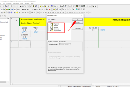
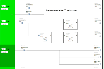
PLC ProgrammingPLC Program for Tank Filling

NETWORK 1 :-

Here we used normal logic for START/STOP cycle.lathing function is used here.

NETWORK 2 :-

Priority selection logic is used in this network. If both the tanks are empty,priority for tank 1 will be activated.

NETWORK 3 :-

If tank 2 is low , priority for tank 2 will be ON.

NETWORK 4 :-

If tank 1 level is low and priority of tank 1 is ON, tank 1 feeding valve will be ON

NETWORK 5 :-

If tank 2 is low and tank 1 priority is not activated, tank 2 feeding valve will be ON.

Note:-Above application may be different from actual application. We can also make this application by using other PLC also. This example is only for explanation purpose. This is the simple concept of priority for multiple tanks in conveying system; we can use this concept in other examples also.

All parameters and graphical representations considered in this example are for explanation purpose only, parameters or representation may be different in actual applications. Also all interlocks are not considered in the application.

Author : Bhavesh

If you liked this article, then please subscribe to our YouTube Channel for PLC and SCADA video tutorials.

You can also follow us on Facebook and Twitter to receive daily updates.

Read Next:

PLC Motor Operation based on Time

Traffic Light Control using PLC

PLC Automatic Control of Outputs

PLC Level Control of Two Tanks

Making PLC Multi Way Switches

Don't Miss Our Updates
Be the first to get exclusive content straight to your email.
We promise not to spam you. You can unsubscribe at any time.
Invalid email address
You've successfully subscribed !

Continue Reading

Split Range Control Application using PLC Ladder Logic
Real-Time Clock in Omron PLC? – CX Programmer
Boolean Logic to PLC Programming
PLC Digital Input and Digital Output Modules
PLC Program for Fish Feeding System
Compare Servo Motor and Stepper Motor
Share This Article
Facebook Whatsapp Whatsapp LinkedIn Copy Link
Share
1 Comment
  • Jawad says:
    August 23, 2020 at 1:07 pm

    You have not mentioned the condition for high level

    Reply

Leave a Reply Cancel reply

Your email address will not be published. Required fields are marked *

Stay Connected

128.3kFollowersLike
69.1kFollowersFollow
208kSubscribersSubscribe
38kFollowersFollow

Categories

Explore More

I&C Engineer Roles & Responsibilities – Instrumentation Design
PLC Program for Automatic Parameter Initialization When Power UP
Up Down Counter Instruction in PLC
Testing and Validation in PLC Development
What are User Defined Function Blocks in PLC?
Siemens PLC Interview Questions and Answers
What is an RTU? – Remote Terminal Unit
Troubleshooting PLC Permissive Inputs

Keep Learning

Types of PLC

#14 PLC Best Practices – Restrict Third-party Data Interfaces

Top 100 PLC Projects List

Top 100 PLC Projects List

PLC Program for Trash Compactor

PLC Program for Trash Compactor

Compare DCS, PLC, RTU

Difference between DCS, PLC, and RTU ?

PLC FBD Example for Tank Liquid Heating Control by Steam Flow

PLC FBD Example for Tank Liquid Heating Control by Steam Flow

PLC Program to Control Level of Two Tanks

PLC Level Control of Two Tanks

Types of Scan Time in a PLC

Programmable Logic Controller (PLC) Scan Time – Types, Theory

Omron PLC Mixing System

Mixing Program with Timers and Counters in Omron PLC

Learn More

How to Test a Motor using Megger

How to Test a Motor using Megger?

Concept of DCS in Industrial Automation

Concept of DCS in Industrial Automation

PLC Data comparison instructions

PLC Data Comparison Instructions

How are Data Centers Cooled

How are Data Centers Cooled?

Single Bearing Motor Stator Winding

Critical High KiloWatt Motor Winding Burnout Threats

Instrument Skid

What is an Instrument Skid? – Example of Metering Skid

Pressure Gauge Maintenance and Troubleshooting

Pressure Gauge Maintenance and Troubleshooting

What is a Inductive Proximity Switch

What is a Inductive Proximity Switch ?

Follow US
All rights reserved. Reproduction in whole or in part without written permission is prohibited.
Welcome Back!

Sign in to your account

Username or Email Address
Password

Lost your password?