Inst ToolsInst ToolsInst Tools
  • Courses
  • Automation
    • PLC
    • Control System
    • Safety System
    • Communication
    • Fire & Gas System
  • Instrumentation
    • Design
    • Pressure
    • Temperature
    • Flow
    • Level
    • Vibration
    • Analyzer
    • Control Valve
    • Switch
    • Calibration
    • Erection & Commissioning
  • Interview
    • Instrumentation
    • Electrical
    • Electronics
    • Practical
  • Q&A
    • Instrumentation
    • Control System
    • Electrical
    • Electronics
    • Analog Electronics
    • Digital Electronics
    • Power Electronics
    • Microprocessor
  • Request
Search
  • Books
  • Software
  • Projects
  • Process
  • Tools
  • Basics
  • Formula
  • Power Plant
  • Root Cause Analysis
  • Electrical Basics
  • Animation
  • Standards
  • 4-20 mA Course
  • Siemens PLC Course
Reading: PLC Latching Function
Share
Notification Show More
Font ResizerAa
Inst ToolsInst Tools
Font ResizerAa
  • Courses
  • Design
  • PLC
  • Interview
  • Control System
Search
  • Courses
  • Automation
    • PLC
    • Control System
    • Safety System
    • Communication
    • Fire & Gas System
  • Instrumentation
    • Design
    • Pressure
    • Temperature
    • Flow
    • Level
    • Vibration
    • Analyzer
    • Control Valve
    • Switch
    • Calibration
    • Erection & Commissioning
  • Interview
    • Instrumentation
    • Electrical
    • Electronics
    • Practical
  • Q&A
    • Instrumentation
    • Control System
    • Electrical
    • Electronics
    • Analog Electronics
    • Digital Electronics
    • Power Electronics
    • Microprocessor
  • Request
Follow US
All rights reserved. Reproduction in whole or in part without written permission is prohibited.
Inst Tools > Blog > PLC Tutorials > PLC Latching Function

PLC Latching Function

PLC Latching function is a self-maintaining circuit in that, after being energized, it maintains that state until another input is received.

Last updated: November 2, 2023 2:33 pm
Editorial Staff
PLC Tutorials
No Comments
Share
3 Min Read
SHARE

There are often situations where it is necessary to hold an output energized, even when the input ceases.

A simple example of such a situation is a motor, which is started by pressing a push button switch. Though the switch contacts do not remain closed, the motor is required to continue running until a stop push button switch is pressed.

The term latch circuit is used for the circuit used to carry out such an operation. It is a self-maintaining circuit in that, after being energized, it maintains that state until another input is received.

PLC Latching Function

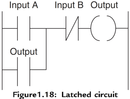
An example of a latch circuit is shown in Figure 1.18. When the input A contacts close, there is an output. However, when there is an output, another set of contacts associated with the output closes.
PLC Latching Function

These contacts form an OR logic gate system with the input contacts. Thus, even if the input A opens, the circuit will still maintain the output energized. The only way to release the output is by operating the normally closed contact B.

Also Read: PLC Logic Functions

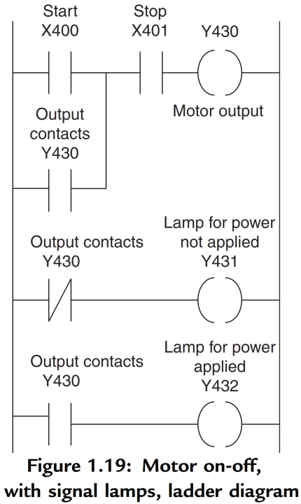
As an illustration of the application of a latching circuit, consider a motor controlled by stop and start push button switches and for which one signal light must be illuminated when the power is applied to the motor and another when it is not applied.

Figure 1.19 shows the ladder diagram with Mitsubishi notation for the addresses.
PLC Motor Logic Application

Note that  the stop contacts  X401 are shown as being programmed as open.  If the stop  switch used is normally closed then X401 receives a start-up signal to close. This gives a safer operation than  programming  X401 as normally closed.

X401 is closed when the program is started. When X400 is momentarily closed, Y430 is energized and its contacts close. This results in latching and also the switching off of Y431 and the switching on of Y432.

To switch the motor off, X401 is pressed and opens. Y430 contacts open in the top rung and third rung, but close in the second rung. Thus Y431 comes on and Y432 off.

Latching is widely used with start-ups so that the initial switch on of an application becomes latched on.

Also Read: Introduction to PLC Ladder Diagrams

If you liked this article, then please subscribe to our YouTube Channel for PLC and SCADA video tutorials.

You can also follow us on Facebook and Twitter to receive daily updates.

Read Next:
  • Latches Objective Questions
  • Solenoid Operated Valves and Latching Valves
  • D Latch
  • PLC Motor Logic with START, STOP, TEST Push buttons
  • Concept of Latching in PLC
Don't Miss Our Updates
Be the first to get exclusive content straight to your email.
We promise not to spam you. You can unsubscribe at any time.
Invalid email address
You've successfully subscribed !

Continue Reading

Simulation of Studio 5000 and FactoryTalk View Studio
Examples of SCADA and PLC Configuration Systems
Glass Cutting and Polishing Machine: PLC Automation Solution
PLC Digital Input and Digital Output Modules
4-20 mA Transmitter Wiring Types : 2-Wire, 3-Wire, 4-Wire
PLC Program for Alarm Security System
Share This Article
Facebook Whatsapp Whatsapp LinkedIn Copy Link
Share
Leave a Comment

Leave a Reply Cancel reply

Your email address will not be published. Required fields are marked *

Stay Connected

128.3kFollowersLike
69.1kFollowersFollow
210kSubscribersSubscribe
38kFollowersFollow

Categories

Explore More

Count and Pack Objects from Conveyor using PLC Ladder Logic
Allen Bradley PLC ControlLogix Hardware
Documentation and Change Control of PLC or DCS Systems
How to Save a PLC Project to a Micro Memory Card?
PLC Program for Controlling a Water Pump with 3 Power Sources
Allen Bradley PLC Subroutines
How to Wire a Field instrument to Control Room with Example
Increment & Decrement Instructions in CX-Programmer (OMRON)

Keep Learning

OB and FB Blocks in Siemens PLC

Procedure for Siemens S7-300 Download from PC to PLC

PLC Pump Control

PLC Pump Control: 10 seconds ON & 20 seconds OFF

STL Programming - SET, RESET, ASSIGN

STL Programming – SET, RESET, ASSIGN

Difference between Signal Cables and Control Cables

Difference between Signal Cables and Control Cables

Surge Protection Device

What is a Surge Protection Device? – Principle, Types, Advantages

Studio 5000 Define Program or Operator Control in Functional Block Diagram

Studio 5000: Define Program or Operator Control in Functional Block Diagram

Industrial motor control using PLC instruction list programming

PLC Instruction List for Motor Reverse and Forward Direction

SCADA Systems

SCADA Systems

Learn More

H & B Gas Analyzer Principle and Calibration Procedure

Hydrostatic Level Measurement

Hydrostatic Level Measurement

Fisher model 546 I to P transducer

Fisher model 546 I/P transducer

Basics of PID Controllers

PID Controllers in Closed Loop Control Systems – PLC Basics

wedge Flow meter

What is a Segmental Wedge Flow Meter?

Best Instrumentation Engineering Books to Purchase

Best Instrumentation Engineering Books to Purchase

Tags in Functional Block Diagram in Studio 5000

Sheets, Tags, Elements in Functional Block Diagram of Studio 5000

thermocouple types

What is a Thermocouple ?

Menu

  • About
  • Privacy Policy
  • Copyright

Quick Links

  • Learn PLC
  • Helping Hand
  • Part Time Job

YouTube Subscribe

Follow US
All rights reserved. Reproduction in whole or in part without written permission is prohibited.
Welcome Back!

Sign in to your account

Username or Email Address
Password

Lost your password?