Differential pressure sensors are common in the process industry and cover a variety of applications. To understand what a differential pressure sensor is, it becomes important to put it in contrast to other pressure measurement types. The most common types of pressure measurement are absolute, gauge and differential.
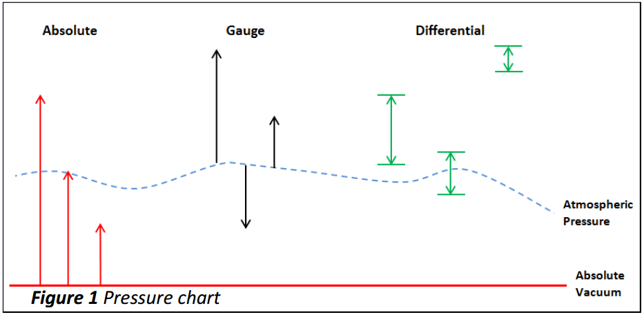
Gauge Pressure: Gauge pressure is the pressure difference in reference to barometric (or atmospheric) pressure as showing in figure 1. This is the most common pressure measurement type in industry today.
Absolute Pressure: Absolute pressure is when zero pressure is referenced to absolute vacuum as shown in figure 1. This is done by pulling a very hard vacuum, achieving as close to absolute zero as possible, and then referencing the zero of the sensor to that vacuum point. Often absolute sensors utilize a gauge sensor and a barometric sensor and calculate the absolute pressure by subtracting the barometric pressure from the gauge pressure.
Differential Pressure: Differential pressure (DP) can be independent of the atmospheric and absolute pressures. It is the pressure difference between two applied pressures and as shown in figure 1. These sensors are very useful in determining the pressure difference between two places or systems and are often used in flow calculation, filtering, fluid level, density, and viscosity.
So now that we’ve reviewed the different pressure types and we know what differential pressure is and how it compares to other pressure measurement types. Now, we can consider how we calibrate a DP sensor and some of the challenges associated with calibration of DP sensors. First, let’s start with the challenges.
Common Challenges in Calibrating DP Sensors
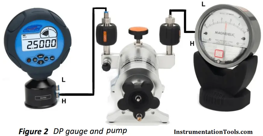
Producing a stable, controlled pressure – to have a meaningful measurement for calibration we must be able to have stable pressure generation from a pressure source, such as a pump or a controller. DP sensors can be very sensitive, so a solution that will produce and hold a stable pressure is very important. Also, the pump or controller needs to have sufficient resolution to be able to exactly generate the desired pressure points. Producing a stable, controlled pressure with high resolution is often a challenge because many pump solutions rely on check valves, or non-returning valves, within the pump as shown in Figure 2 : DP gauge and pump stability. These check valves are prone to leaks over time and use and are often the source of frustration when trying to hold highly stable pressures for a DP sensors calibration.
Temperature effects – Possibly the largest challenge to calibrating DP sensors has to do with the impact of the environmental temperature on the DP sensor and the calibration standards. Because many DP sensors are measuring very low full scale (FS) pressures, a small change in temperature can amount to a very noticeable change in pressure. This change in temperature often equates to constant instability in both the sensor being tested and the calibration standard (both reference gauge and pump).
Changing atmospheric pressure – Several DP sensor manufacturers recommend the calibration be performed with the reference port (or low port) be open to atmosphere. The challenge with this requirement is that throughout a calibration, the atmospheric pressure is constantly changing which influences the stability and repeatability of the calibration results.
Methods of Calibration
Example 1 – Using an pressure pump, DP reference gauge with the DUT’s reference port open to atmosphere
Required Equipment:
Low pressure calibration pump
Device under test
Reference DP Gauge
Lines and fittings to connect from the gauges to the pump
Connection (See figure 2)
Both the high ports of each gauge are connected into the calibration pump
The reference or low ports of each gauge are left open to atmosphere
Ensure the DUT is in the proper orientation (typically vertical or horizontal)
Procedure
Depending on the DUT, you may need to exercise the gauge multiple times to its full scale.
Ensure the vent valve is open and zero both the reference gauge and the DUT (assuming the DUT is a digital gauge that requires regular zeroing).
Close the vent valve and proceed to the next calibration points and record the data when the measurement is stable.
Increase the Pressure by using pump and note down the readings in DUT & Reference gauge.
Typically, 3-5 calibration points are taken both upward then downward so as to determine hysteresis.
Pros: This method is inexpensive and the set up is easy.
Cons: You’ll need to account for barometric pressure and temperature changes throughout the test. Depending on the environmental conditions this can produce very unstable measurements. This is the least accurate method for calibration of DP sensors.
Example 2 – Using an Low pressure calibration pump, DP reference gauge with the DUT’s reference ports connected together
Required Equipment:
Low pressure calibration pump
Device under test
Reference DP Gauge
Lines and fittings to connect from the gauges to the pump and the gauges together
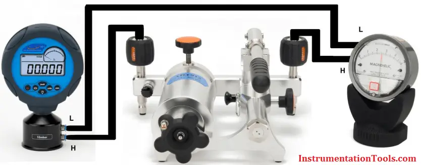
Connection (see figure 3)
Both high ports of each gauge are connected into the calibration pump.
The reference or low ports of each gauge are connected together.
Ensure the DUT is in the proper orientation (typically vertical or horizontal).
Note: In this method pressure is generated on both the high and low pressure lines and the DP is measured by the reference gauge. Depending on the DP range required the best solution to reach the full scale of the DUT.
Procedure
Depending on the DUT, you may need to exercise the gauge multiple times to its full scale
Recording the zero point may vary depending on the type of DUT. If the DUT is a digital gauge, then keep the reference gauge and the DUT reference ports connected together and zero both gauges. If the DUT is an analog gauge that doesn’t require a regular zero, then disconnect both reference ports and leave them open to atmosphere to zero the gauges. After recording the zero point connect both the reference ports together and proceed through the calibration.
Close the vent valve and proceed to the next calibration points and record the data when the measurement is stable.
Increase the Pressure by using pump and note down the readings in DUT & Reference gauge.
Typically, 3-5 calibration points are taken both upward then downward so as to determine hysteresis
Pros: This method is inexpensive and better accounts for atmospheric pressure changes throughout the test. The stability at each point is improved from the first example.
Cons: The set up is more complicated than the first example and temperature effects can potentially have a larger impact than the first example because we have a sealed system with the low (reference) lines being connected.
Example 3 – Using the automated calibration Equipment
Required Equipment:
Automatic Calibrator
Device under test
Lines and fittings to connect the DP gauge to the Calibrator
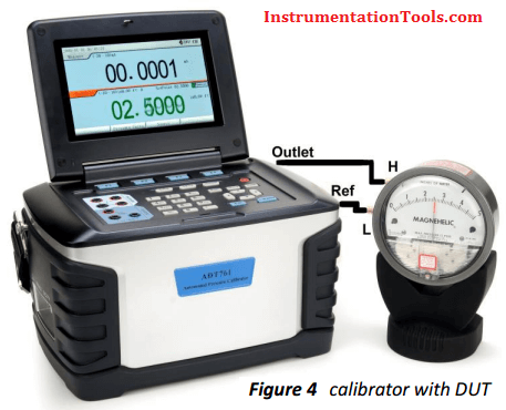
Connection (see figure 4)
Connect the high port of the DP gauge to the OUTLET port of the Automatic Calibrator Equipment
Connect the low port of the DP gauge to the REF port of the Automatic Calibrator Equipment.
Ensure the DUT is in the proper orientation (typically vertical or horizontal).
Procedure
Depending on the DUT, you may need to exercise the gauge multiple times to its full scale.
Program in a task and run an automated test which will automatically generate the pressure, stabilize the measurement, and allow for the DP gauge reading to be recorded.
Typically, 3-5 calibration points are taken both upward then downward and the Calibrator will automatically calculate the hysteresis and display the test results with pass/fail criteria.
Pros: This method is fully- or semi-automated depending on the DUT. Measurements are controlled and stability is ensured by the Calibrator controller. The Calibrator is much less influenced by changes in temperature and barometric pressure than the previous examples. Results are automatically displayed and calculated. The Calibrator can calibrate pressure gauges and transmitters.
Cons: The equipment is more costly than the previous examples.
Source : additel
Also Read: Pressure Switch Calibration Procedure


Excelentes exercícios!
Muito bons!
Nicely Explained. Good
i feel excellent blog for gain realtime experiece in instrumentation
Differential pressure transmeter what is pressure difrence pl understand me.