Inst ToolsInst ToolsInst Tools
  • Ask
  • Courses
  • Videos
  • Q & A
    • Interview
      • Instrumentation
      • Electronics
      • Electrical
      • Practical Questions
    • MCQ
      • Instrumentation MCQ
      • Electrical MCQ
      • Electronics MCQ
      • Control Systems MCQ
      • Analog Electronics MCQ
      • Digital Electronics MCQ
      • Power Electronics MCQ
      • Microprocessor MCQ
      • Multiple Choice Questions
  • EE
    • Electronics
      • Electronics Q & A
      • Electronic Basics
      • Electronic Devices & Circuits
      • Electronics Animation
      • Digital Electronics
    • Electrical
      • Electrical Basics
      • Electrical Q & A
      • Power Electronics
      • Electrical Machines
      • Electrical Animation
      • Power Systems
      • Switchgear & Protection
      • Transmission & Distribution
  • Measure
    • Control Valves
    • Calibration
    • Temperature
    • Pressure
    • Flow
    • Level
    • Analyzers
    • Switches
    • Vibration
    • Solenoid Valve
  • Control
    • PLC Tutorials
    • Control Systems
    • Safety Instrumented System (SIS)
    • Communication
    • Fire & Gas System
  • More
    • Design
    • Tools
    • Animation
    • Basics
    • Formulas
    • Standards
    • TextBooks
    • Common
    • Software
    • Excel Tools
    • Erection & Commissioning
    • Process Fundamentals
    • Videos
    • Books
Search
All rights reserved. Reproduction in whole or in part without written permission is prohibited.
Reading: Impedance in RL Circuits
Share
Notification Show More
Font ResizerAa
Inst ToolsInst Tools
Font ResizerAa
  • Courses
  • PLC Tutorials
  • Control Systems
Search
  • Ask
  • Courses
  • Videos
  • Q & A
    • Interview
    • MCQ
  • EE
    • Electronics
    • Electrical
  • Measure
    • Control Valves
    • Calibration
    • Temperature
    • Pressure
    • Flow
    • Level
    • Analyzers
    • Switches
    • Vibration
    • Solenoid Valve
  • Control
    • PLC Tutorials
    • Control Systems
    • Safety Instrumented System (SIS)
    • Communication
    • Fire & Gas System
  • More
    • Design
    • Tools
    • Animation
    • Basics
    • Formulas
    • Standards
    • TextBooks
    • Common
    • Software
    • Excel Tools
    • Erection & Commissioning
    • Process Fundamentals
    • Videos
    • Books
Follow US
All rights reserved. Reproduction in whole or in part without written permission is prohibited.
Inst Tools > Blog > Electrical Theory > Impedance in RL Circuits

Impedance in RL Circuits

Last updated: July 30, 2018 8:01 pm
Editorial Staff
Electrical Theory
No Comments
Share
1 Min Read
SHARE

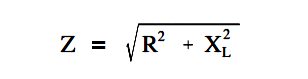
Impedance is the resultant of phasor addition of R and XL.

The symbol for impedance is Z.

Impedance is the total opposition to the flow of current and is expressed in ohms.

The below Equation is the mathematical representation of the impedance in an RL circuit.

Impedance in RL Circuits

Example:

If a 100 Ω resistor and a 60 Ω XL are in series with a 115V applied voltage (Figure 6), what is the circuit impedance?

Simple RL Circuit

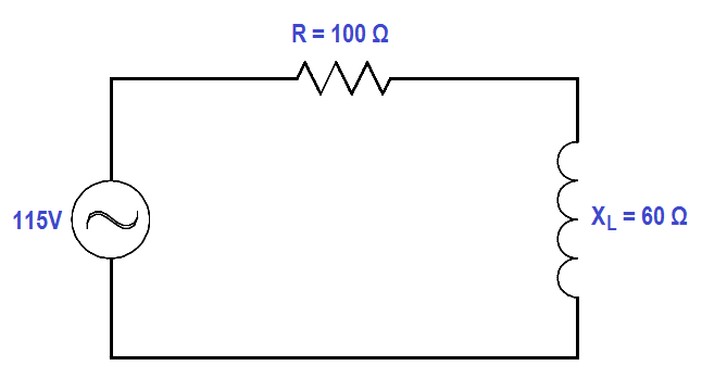
Figure 6 : Simple R-L Circuit

Solution:

Impedance in RL Circuits

Z = √ (1002 + 602)

Z = √ 13600

Z = 116.6 Ω

Don't Miss Our Updates
Be the first to get exclusive content straight to your email.
We promise not to spam you. You can unsubscribe at any time.
Invalid email address
You've successfully subscribed !
Circuit Breaker Control Circuit
Power Triangle
Parallel Open Circuit Faults
Series-Wound Motor
AC Generator Voltage Regulators
Share This Article
Facebook Whatsapp Whatsapp LinkedIn Copy Link
Share
Leave a Comment

Leave a Reply Cancel reply

Your email address will not be published. Required fields are marked *

Stay Connected

128.3kFollowersLike
69.1kFollowersFollow
208kSubscribersSubscribe
38kFollowersFollow

Categories

Recent Comments

  • Guifty Shimica on Top Non-PLC Certification Courses for Automation Professionals
  • Guifty Shimica on Top Non-PLC Certification Courses for Automation Professionals
  • MIHARITSOA Aina Sitraka on Top Non-PLC Certification Courses for Automation Professionals
  • Vaishnavi on Free Instrumentation Course for Trainee Engineers

Related Articles

Calculate Power in Series RL Circuit

Calculate Power in Series RL Circuit

Three Phase Transformer Connections

Three Phase Transformer Connections

Motor Rotating Magnetic Field

AC Motor Theory

Two Wattmeters to Measure 3 Phase Power

Three Phase Wattmeter

Total Resistance in a Parallel Circuit

Resistance in Parallel Circuits

Compounded DC Generator

Compound Generators

Center Tap Full-Wave Rectifier

Full-Wave Rectifier Circuit

Generator Action in a Motor

What is Synchroscope ?

More Articles

Engineers Interview Android App

Electrical Machines Questions and Answers

Speed Control of DC Motors Quiz

Drum water level control

Closed Loop Control System : Boiler Water Level Control System

Ultrasonic Sensors Objective Questions

Ultrasonic Sensors Objective Questions

Gas Turbine Temperature Control using Siemens Tia Portal

Gas Turbine Temperature Alarms using Siemens TIA Portal

Color detection PLC logic

Conveyor Sorting System with Color Detection PLC Logic

DP-Level-Measurement-Calculation-Above-Tapping-Point-Open-Tank

Differential Pressure (DP) Level transmitter Installed Above Tapping Point

Coriolis Mass Flowmeter Principle

Coriolis Mass Flow Sensor Theory

Follow US
All rights reserved. Reproduction in whole or in part without written permission is prohibited.
Welcome Back!

Sign in to your account

Username or Email Address
Password

Lost your password?