Inst ToolsInst ToolsInst Tools
  • Courses
  • Automation
    • PLC
    • Control System
    • Safety System
    • Communication
    • Fire & Gas System
  • Instrumentation
    • Design
    • Pressure
    • Temperature
    • Flow
    • Level
    • Vibration
    • Analyzer
    • Control Valve
    • Switch
    • Calibration
    • Erection & Commissioning
  • Interview
    • Instrumentation
    • Electrical
    • Electronics
    • Practical
  • Q&A
    • Instrumentation
    • Control System
    • Electrical
    • Electronics
    • Analog Electronics
    • Digital Electronics
    • Power Electronics
    • Microprocessor
  • Request
Search
  • Books
  • Software
  • Projects
  • Process
  • Tools
  • Basics
  • Formula
  • Power Plant
  • Root Cause Analysis
  • Electrical Basics
  • Animation
  • Standards
  • 4-20 mA Course
  • Siemens PLC Course
Reading: Applying Kirchhoff’s Current Law
Share
Font ResizerAa
Inst ToolsInst Tools
Font ResizerAa
  • Courses
  • Design
  • PLC
  • Interview
  • Control System
Search
  • Courses
  • Automation
    • PLC
    • Control System
    • Safety System
    • Communication
    • Fire & Gas System
  • Instrumentation
    • Design
    • Pressure
    • Temperature
    • Flow
    • Level
    • Vibration
    • Analyzer
    • Control Valve
    • Switch
    • Calibration
    • Erection & Commissioning
  • Interview
    • Instrumentation
    • Electrical
    • Electronics
    • Practical
  • Q&A
    • Instrumentation
    • Control System
    • Electrical
    • Electronics
    • Analog Electronics
    • Digital Electronics
    • Power Electronics
    • Microprocessor
  • Request
Follow US
All rights reserved. Reproduction in whole or in part without written permission is prohibited.
Inst Tools > Blog > Electrical Theory > Applying Kirchhoff’s Current Law

Applying Kirchhoff’s Current Law

Last updated: July 23, 2018 4:27 pm
Editorial Staff
Electrical Theory
No Comments
Share
3 Min Read
SHARE

Kirchhoff’s second law is called his current law and states: “At any junction point in a circuit, the current arriving is equal to the current leaving.” Thus, if 15 amperes of current arrives at a junction that has two paths leading away from it, 15 amperes will divide among the two branches, but a total of 15 amperes must leave the junction.

We are already familiar with Kirchhoff’s current law from parallel circuits, that is, the sum of the branch currents is equal to the total current entering the branches, as well as the total current leaving the branches (Figure 35).

Illustration of Kirchhoff’s Current Law

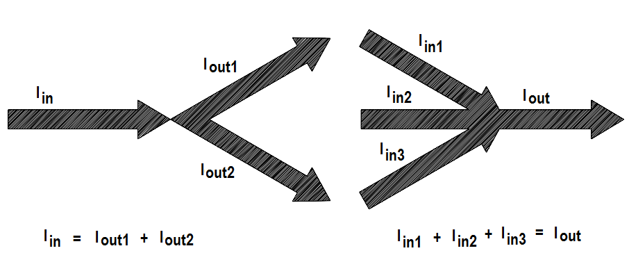
Figure 35 Illustration of Kirchhoff’s Current Law

In equation form, Kirchhoff’s current law may be expressed:

Iin – Iout  = 0

Iin = Iout 

Normally Kirchhoff’s current law is not used by itself, but with the voltage law, in solving a problem.

Example:

Find I2 in the circuit shown in Figure 36 using Kirchhoff’s voltage and current laws.

Current Law
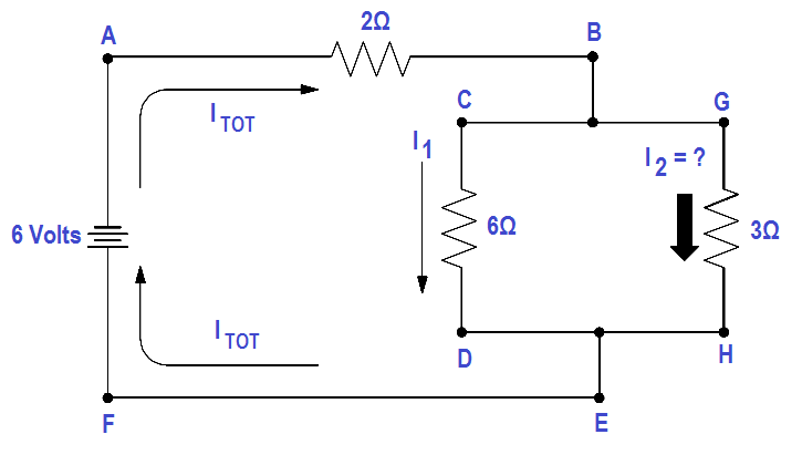
Figure 36 Using the Current Law

Solution:

First, apply Kirchhoff’s voltage law to both loops.

Loop ABCDEF

∑ IR = ∑ E source

2 Itotal + 6I1 = 6

Loop ABGHEF

∑ IR = ∑ E source

2 Itotal + 3I2 = 6

Since Kirchhoff’a current law states Itotal =I1 +I2 , substitute (I1 +I2 ) in the place of Itotal in both loop equations and simplify.

Loop ABCDEF

2 (I1+ I2) +6 I1 = 6
2 I1+2 I2+6 I1= 6
8I1 +2I2= 6

Loop ABGHEF

2 (I1+ I2) +3 I2 = 6
2 I1+2 I2+3I2= 6
2I1 +5I2= 6

We now have two equations and two unknowns and must eliminate I1 to find I2 .

One way is to multiply Loop ABGHEF equation by four, and subtract Loop ABCDEF equation from the result.

Multiply by 4:

4 (2I1 +5I2 = 6 )

8I1 +20I2 + 24

Subtract :

8I1 +20I2 = 24

-(8I1 +2I2 = 6)

——————-

18I2 = 18

——————-

Now we have an equation with only I2 , which is the current we are looking for.

18I2 = 18

I2 = 18/18 = 1 amp

This circuit could have been solved simply by using Ohm’s Law, but we used Kirchhoff’s Laws to show the techniques used in solving complex circuits when Ohm’s Law cannot be used.

Don't Miss Our Updates
Be the first to get exclusive content straight to your email.
We promise not to spam you. You can unsubscribe at any time.
Invalid email address
You've successfully subscribed !

Continue Reading

Synchronous Motors
Low Voltage Air Circuit Breaker Principle
Transformer Mutual Induction
Power Factor Meter Principle
Current Division
Magnetic Circuits
Share This Article
Facebook Whatsapp Whatsapp LinkedIn Copy Link
Share
Leave a Comment

Leave a Reply Cancel reply

Your email address will not be published. Required fields are marked *

Stay Connected

128.3kFollowersLike
69.1kFollowersFollow
210kSubscribersSubscribe
38kFollowersFollow

Categories

Explore More

Generator Action in a Motor
Y and Delta Resistor Network Calculations
Impedance in RC Circuits
Induction Motor Torque Versus Slip
Series Circuit
Calculate Power in Series RC Circuit
Motor Controllers
Low Voltage Protection (LVP) and Low Voltage Release (LVR)

Keep Learning

Left-Hand Rule for Generators

DC Generator Theory

Parallel Circuit

Parallel Circuit

What is electrical transformer

Transformer Impedance Ratio

Batteries Connected in Parallel

Battery Operation : Series and Parallel

Parallel Circuit Unknown Resistance

Simplified Formulas for Parallel Circuit Resistance Calculations

Three Phase To Single Phase Wiring Connections

Single Phase Power Wiring Schemes

Core-Type Transformer

Transformer Theory of Operation

Developing a Sine-Wave Voltage of Motor

AC Generation

Learn More

Allen-Bradley MicroLogix controller

Programmable Logic Controller (PLC) Questions and Answers – 15

Types of Potentiometers

Types of Potentiometers – What is a Potentiometer? – Applications

0-10 VDC to 0-20 mA Conversion

How to Convert Voltage to Current using Resistor ?

BPCS Control System and ESD Safety System of Delta-V DCS

BPCS Control System and ESD Safety System of Delta-V DCS

Thermocouple Software compensation

Thermocouple Software compensation

Top 100 Microcontrollers Project Ideas

Top 100 Microcontrollers Project Ideas

Password Protect Apps and Files

5 Best Mobile Apps to Password Protect Applications and Files

span gas cylinders

Analyzer Sample Systems

Menu

  • About
  • Privacy Policy
  • Copyright

Quick Links

  • Learn PLC
  • Helping Hand
  • Part Time Job

YouTube Subscribe

Follow US
All rights reserved. Reproduction in whole or in part without written permission is prohibited.
Welcome Back!

Sign in to your account

Username or Email Address
Password

Lost your password?