Inst ToolsInst ToolsInst Tools
  • Courses
  • Automation
    • PLC
    • Control System
    • Safety System
    • Communication
    • Fire & Gas System
  • Instrumentation
    • Design
    • Pressure
    • Temperature
    • Flow
    • Level
    • Vibration
    • Analyzer
    • Control Valve
    • Switch
    • Calibration
    • Erection & Commissioning
  • Interview
    • Instrumentation
    • Electrical
    • Electronics
    • Practical
  • Q&A
    • Instrumentation
    • Control System
    • Electrical
    • Electronics
    • Analog Electronics
    • Digital Electronics
    • Power Electronics
    • Microprocessor
  • Request
Search
  • Books
  • Software
  • Projects
  • Process
  • Tools
  • Basics
  • Formula
  • Power Plant
  • Root Cause Analysis
  • Electrical Basics
  • Animation
  • Standards
  • 4-20 mA Course
  • Siemens PLC Course
Reading: PLC Program for Entry and Exit Control of Car Parking
Share
Font ResizerAa
Inst ToolsInst Tools
Font ResizerAa
  • Courses
  • Design
  • PLC
  • Interview
  • Control System
Search
  • Courses
  • Automation
    • PLC
    • Control System
    • Safety System
    • Communication
    • Fire & Gas System
  • Instrumentation
    • Design
    • Pressure
    • Temperature
    • Flow
    • Level
    • Vibration
    • Analyzer
    • Control Valve
    • Switch
    • Calibration
    • Erection & Commissioning
  • Interview
    • Instrumentation
    • Electrical
    • Electronics
    • Practical
  • Q&A
    • Instrumentation
    • Control System
    • Electrical
    • Electronics
    • Analog Electronics
    • Digital Electronics
    • Power Electronics
    • Microprocessor
  • Request
Follow US
All rights reserved. Reproduction in whole or in part without written permission is prohibited.
Inst Tools > Blog > Guest Articles > PLC Program for Entry and Exit Control of Car Parking

PLC Program for Entry and Exit Control of Car Parking

PLC program for car parking entry and exit gates control explained with programming solution and diagram.

Last updated: November 3, 2023 11:44 am
Editorial Staff
Guest Articles PLC Tutorials
2 Comments
Share
6 Min Read
SHARE

This is a PLC Program for Entry/Exit control of the basement or underground car parking.

Contents
PLC Car ParkingProblem DiagramProblem SolutionList of Inputs and OutputsPLC Ladder Diagram for Entry/Exit control of car parkingProgram DescriptionResult

PLC Car Parking

Problem Description

Due to crowded area we face lots of problems of vehicle parking at basement or underground at shopping mall, hotels, complex etc.

This is happening due to contradiction between the rapidly growing number of vehicles and limited parking spaces in malls, shop and complex in cities results in the phenomenon of “difficult parking and disorderly parking”.

Current parking problem has serious impacts on people’s quality of life and the running of roads.

Problem Diagram

PLC Car Parking Program

Problem Solution

By simple automation we can reduce the car parking problem at basement or underground in shopping mall, hotels, complex etc. The Entry/Exit at basement is a single lane passage and it needs traffic lights to control cars.

Here we consider two lights indication for cars control. Red lights prohibit cars entering or leaving while green lights allow cars entering and leaving.

When car enters at the passage from the entry of the ground floor, both red lights (ground floor and basement) will be ON.

Other car entering and leaving is prohibited during the process till the car passes through the single passage.

When passage is clear both green lights (ground floor and basement) will be ON and allow other cars entering from the ground floor or basement.

Initially we will keep green lights ON and red light OFF

List of Inputs and Outputs

Inputs List

  • Main SWITCH : I0.0
  • Sensor S1 for ground floor Entry/Exit : I0.1
  • Sensor S2 for basement Entry/Exit : I0.2

Outputs List

  • Green light (Entry/Exit ground floor) : Q0.0
  • Green light (Entry/Exit basement) : Q0.1
  • Red light (Entry/Exit ground floor) : Q0.2
  • Red light (Entry/Exit basement) : Q0.3

M memory coil List

  • M10.0 : Will be ON when car passes sensor S1
  • M10.3 : Will be ON when car Passes sensor S2
  • M0.0 : Positive edge of system ON
  • M0.1 & M11.0 : Positive edge of sensor S1
  • M0.3 & M11.1 : Positive edge of sensor S2
  • M11.2 : Negative edge of sensor S2
  • M11.3 : Negative edge of sensor S1

PLC Ladder Diagram for Entry/Exit control of car parking
PLC Program Car Parking
PLC Scan Cycle
PLC car parking project
car parking PLC
PLC Sensors detect
car parking control using PLC
PLC based automatic car parking system
automatic car parking project using PLC
Car parking using PLC and SCADA

Program Description

In this application we have used Siemens S7-300 PLC and TIA Portal Software for programming.

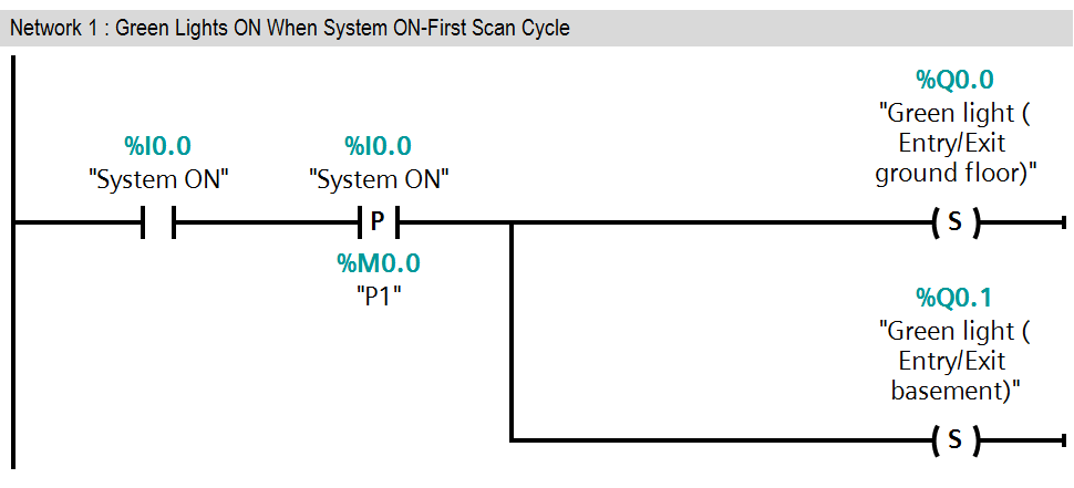
Network 1:

As per above explanation in first network when system is ON (I0.0), initially both green lights (ground floor (Q0.0) and basement (Q0.1)) will be ON. SET instruction is executed and it will set both output Q0.0 and Q0.1.

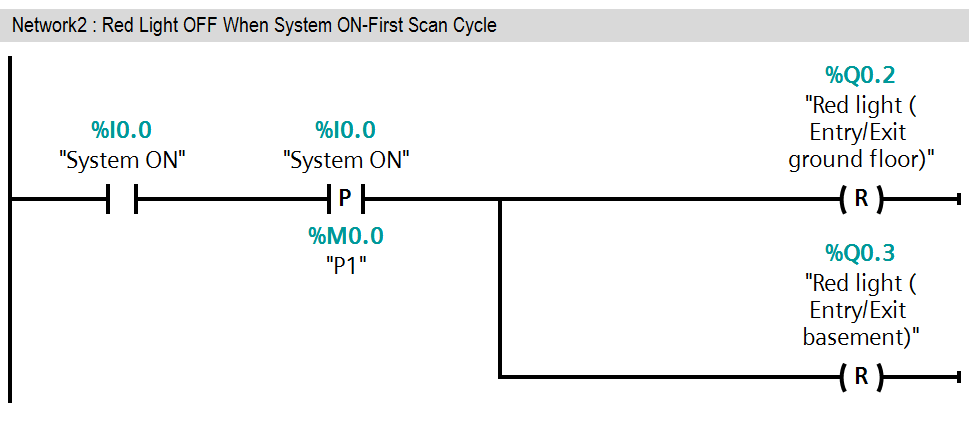
Network 2:

As per above explanation in second network when system is ON (I0.0), initially both red lights (ground floor (Q0.2) and basement (Q0.3)) will be OFF.)

RESET instruction is executed and it will reset both output Q0.2 and Q0.3.

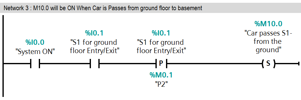
Network 3:

When car enters in the empty passage from the ground floor, sensor S1 (I0.1) will be triggered and with this trigger, memory coil M10.0 will be SET.

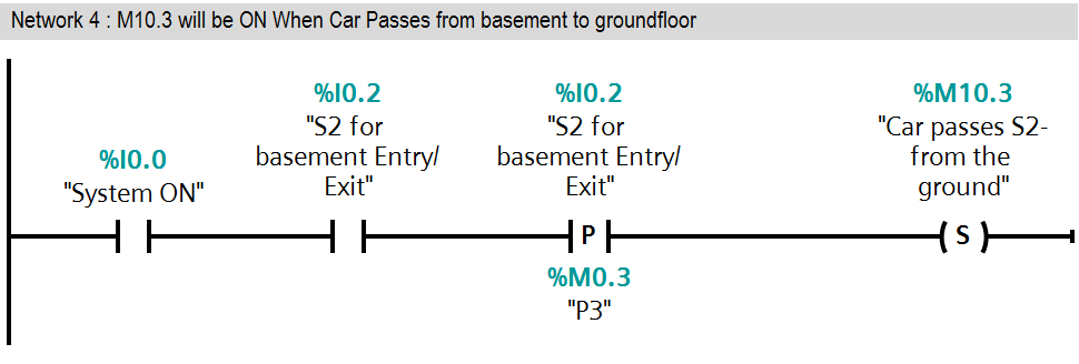
Network 4:

When car enters in the empty passage from the basement, sensor S2 (I0.2) will be triggered and with this trigger, memory coil M10.3 will be SET.

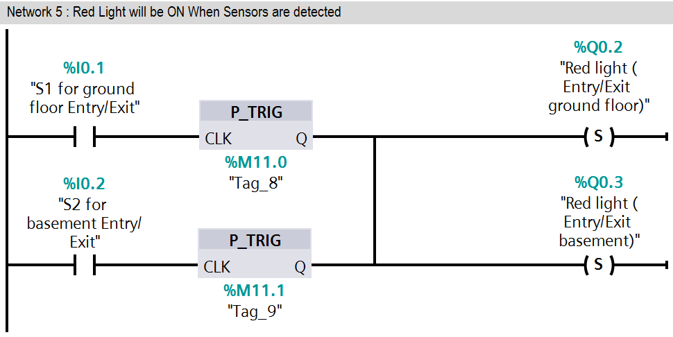
Network 5:

Both red lights will be set by either positive trigger of sensor S1 or sensor S2.

Because when car enters in empty passage then both red lights (Q0.2 & Q0.3) will prohibit car entry/exit from both side.

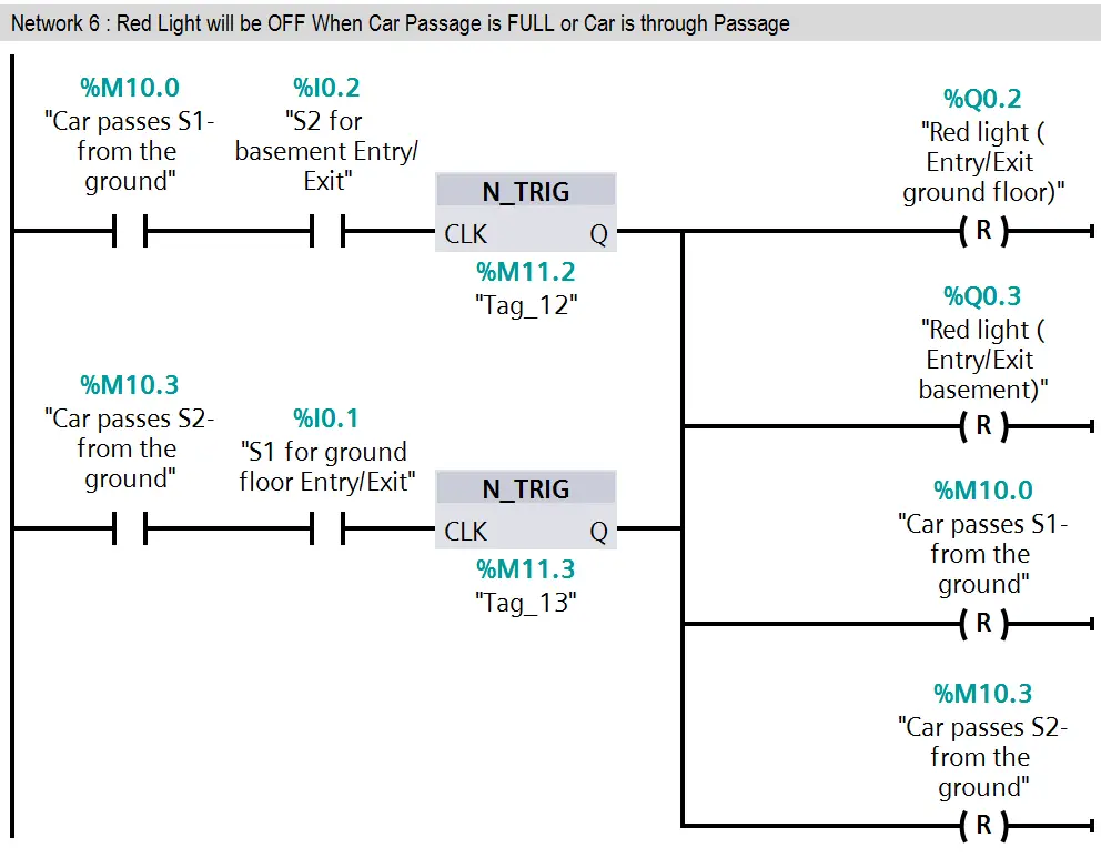
Network 6:

Here we have taken negative trigger of both sensor S1 (I0.1) and S2 (I0.2). so when they triggered red lights (Q0.2 & Q0.3) will be OFF.

When car completely passes empty passage then red lights (Q0.2 & Q0.3) should be OFF.

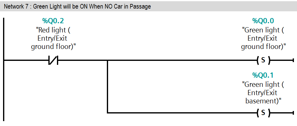
Network 7:

In this network green lights (Q0.0 & Q0.1) will be ON when red lights are OFF.

Green lights (Q0.0 & Q0.1) allow other car for entry or exit.

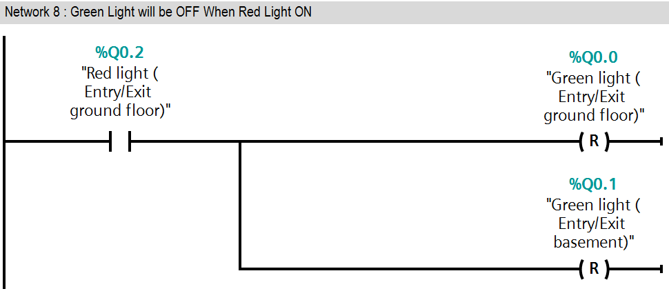
Network 8:

If red lights (Q0.2 & Q0.3) are ON at that time green lights (Q0.0 & Q0.1) should be OFF.

So in this network when red lights (Q0.2 & Q0.3) ON at that time reset instruction will be executed and green lights (Q0.0 & Q0.1) will be OFF

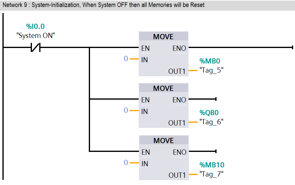
Network 9:

If system ON (I0.0) SWITCH is OFF then all memories should be 0.Here we have taken MOVE instruction for moving zero in all memories (MB0, QB0, and MB10).

This Example is for concept explanation only, not all parameters are considered in this example (such as door open/close system, alarms etc.)

Result

PLC Ladder Logic for Car Parking

Note : The above PLC Logic provided for basic idea about application of PLC in Car Parking Control of Entry/Exit Gates. The Logic is limited and not complete application.

Author : Bhavesh

If you liked this article, then please subscribe to our YouTube Channel for PLC and SCADA video tutorials.

You can also follow us on Facebook and Twitter to receive daily updates.

Read Next:

  • PLC Scaling a Sensor
  • Controls Valve using PLC
  • PLC Math instructions
  • Timer Programming Examples
  • Basics of PLC Programming
Don't Miss Our Updates
Be the first to get exclusive content straight to your email.
We promise not to spam you. You can unsubscribe at any time.
Invalid email address
You've successfully subscribed !

Continue Reading

How to Take Program Backup from Physical PLC? – Siemens PLC
PLC Panel and MCC Panel Interface Signals
How to Save a PLC Project to a Micro Memory Card?
Control Two Motors in Sequence after Time Delay – Circuit, Operation
Ladder Diagram Example using Memory Bits and Set Coils
Write a PLC Program for Selector Machine using Structured Text
Share This Article
Facebook Whatsapp Whatsapp LinkedIn Copy Link
Share
2 Comments
  • rahim says:
    June 21, 2018 at 11:14 am

    Thanks a lot

    Reply
  • Balaji says:
    June 24, 2018 at 5:40 pm

    Great

    Reply

Leave a Reply Cancel reply

Your email address will not be published. Required fields are marked *

Stay Connected

128.3kFollowersLike
69.1kFollowersFollow
210kSubscribersSubscribe
38kFollowersFollow

Categories

Explore More

Introduction to Functional Block Diagram in Studio 5000
What is a Annunciator Panel?
PLC Conveyor Motor Ladder Logic
PLC Programmer Salary and Future Career Scope
PLC Timer Example: Sequential Control of Three Lights with Reset
PLC Pump Control: 10 seconds ON & 20 seconds OFF
Why different PLC Programming Languages were Developed?
Structured Text PLC Programming for Two-Tanks Level Application

Keep Learning

0-10 VDC to 0-20 mA Conversion

How to Convert Voltage to Current using Resistor ?

Moisture Separator

Inhouse Moisture separator for Pneumatic Systems

Delete Siemens CPU Memory

How to Delete the Siemens CPU Memory?

PROFIBUS is also a Master Slave protocol

Compare Modbus, Fieldbus, and Profibus

PLC Karnaugh maps

How to Simplify PLC Coding Using Karnaugh Maps?

Industrial Automation Solution

How to Choose the Right Industrial Automation Solution?

OSI Reference model

SCADA Communication and Protocols

VFD Interview Questions and Answers

VFD Interview Questions and Answers – Electrical Drives

Learn More

SCADA

Top 100+ SCADA Questions

Magnetostrictive Transducers Objective Questions

Magnetostrictive Transducers Objective Questions

PLC Logic Example on Multiple Switches and Motors

PLC Logic Example on Multiple Switches and Motors

PLC and MCC Panel Interface Design

PLC Panel and MCC Panel Interface Signals

H & B Gas Analyzer Principle and Calibration Procedure

Magnetostrictive Level Transmitter Working Principle

Magnetostrictive Level Transmitter Working Principle

Why Damper windings used in synchronous motors

Semiconductor Fuse

What is a Semiconductor Fuse?

Menu

  • About
  • Privacy Policy
  • Copyright

Quick Links

  • Learn PLC
  • Helping Hand
  • Part Time Job

YouTube Subscribe

Follow US
All rights reserved. Reproduction in whole or in part without written permission is prohibited.
Welcome Back!

Sign in to your account

Username or Email Address
Password

Lost your password?