Inst ToolsInst ToolsInst Tools
  • Courses
  • Automation
    • PLC
    • Control System
    • Safety System
    • Communication
    • Fire & Gas System
  • Instrumentation
    • Design
    • Pressure
    • Temperature
    • Flow
    • Level
    • Vibration
    • Analyzer
    • Control Valve
    • Switch
    • Calibration
    • Erection & Commissioning
  • Interview
    • Instrumentation
    • Electrical
    • Electronics
    • Practical
  • Q&A
    • Instrumentation
    • Control System
    • Electrical
    • Electronics
    • Analog Electronics
    • Digital Electronics
    • Power Electronics
    • Microprocessor
  • Request
Search
  • Books
  • Software
  • Projects
  • Process
  • Tools
  • Basics
  • Formula
  • Power Plant
  • Root Cause Analysis
  • Electrical Basics
  • Animation
  • Standards
  • 4-20 mA Course
  • Siemens PLC Course
Reading: Practical Process Control System Questions & Answers – 6
Share
Notification Show More
Font ResizerAa
Inst ToolsInst Tools
Font ResizerAa
  • Courses
  • Design
  • PLC
  • Interview
  • Control System
Search
  • Courses
  • Automation
    • PLC
    • Control System
    • Safety System
    • Communication
    • Fire & Gas System
  • Instrumentation
    • Design
    • Pressure
    • Temperature
    • Flow
    • Level
    • Vibration
    • Analyzer
    • Control Valve
    • Switch
    • Calibration
    • Erection & Commissioning
  • Interview
    • Instrumentation
    • Electrical
    • Electronics
    • Practical
  • Q&A
    • Instrumentation
    • Control System
    • Electrical
    • Electronics
    • Analog Electronics
    • Digital Electronics
    • Power Electronics
    • Microprocessor
  • Request
Follow US
All rights reserved. Reproduction in whole or in part without written permission is prohibited.
Inst Tools > Blog > Practical Questions > Practical Process Control System Questions & Answers – 6

Practical Process Control System Questions & Answers – 6

Last updated: September 26, 2018 5:42 pm
Editorial Staff
Practical Questions
No Comments
Share
3 Min Read
SHARE

This water filter level control system uses an ultrasonic level transmitter to sense the level of water in the filter, and a controller to drive a motor-actuated valve introducing raw water to be filtered:

water filter level control system

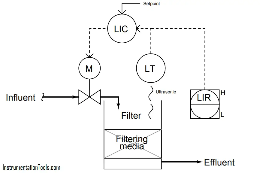
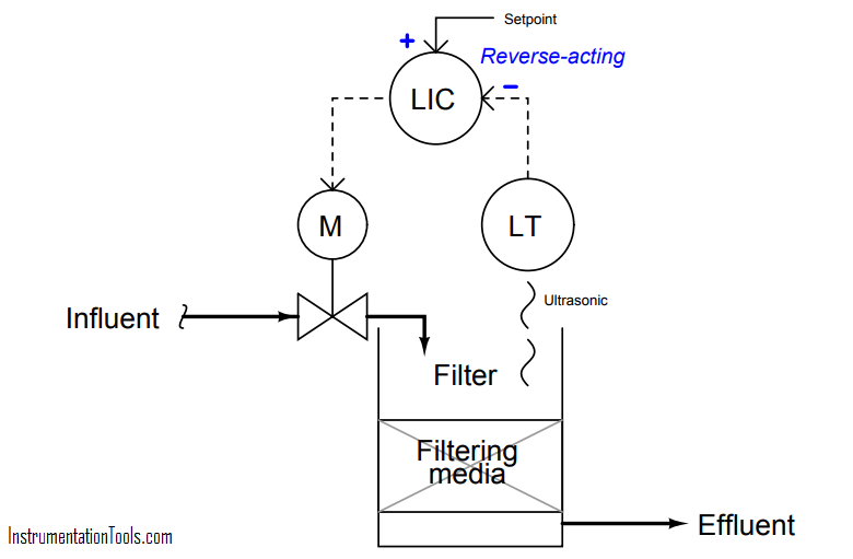
Assuming a direct-acting level transmitter (increasing filter level = increasing signal), and a signal-toopen control valve (increasing controller output signal = wider open valve), determine whether the level controller needs to be configured for direct-action or reverse-action, and explain your reasoning. Annotate the diagram with “+” and “−” symbols next to the PV and SP controller inputs to show more explicitly the relationships between the controller inputs and output.

Next, determine the response of the controller to the following situations. In other words, determine what the controller’s output signal will do when this water level control system is affected in the following ways:

  • A sudden increase in effluent flow rate (clean water demand)
  • Level transmitter fails high (indicating 100% full water level)
  • Control valve actuator fails, driving valve fully open (ignoring controller signal)

More Questions :

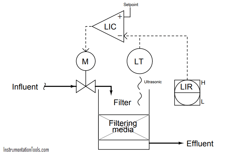
  1. Re-draw the diagram for this water filter level control system, replacing the controller (circle) with an op-amp symbol (triangle), determining the “+” and “−” input assignments on the opamp for PV and SP.
  2. Explain why level control is important in a water filter such as this.
  3. What do the “H” and “L” symbols near the LIR represent?

Answer :

This controller needs to be reverse-acting:

water filter level control system - 1

This re-drawing of the control system uses an opamp symbol in place of the ISA-standard circle used to represent a loop controller:

water filter level control system - 2

  • A sudden increase in effluent flow rate (clean water demand): controller output increases
  • Level transmitter fails high (indicating 100% full water level): controller output decreases
  • Control valve actuator fails, driving valve fully open (ignoring controller signal): controller output decreases

Share Your Answers via Comments

More Questions & Answers :
Practical Process Control System Questions & Answers – 1
Practical Process Control System Questions & Answers – 2
Practical Process Control System Questions & Answers – 3
Practical Process Control System Questions & Answers – 4
Practical Process Control System Questions & Answers – 5
Practical Process Control System Questions & Answers – 6
Practical Process Control System Questions & Answers – 7
Practical Process Control System Questions & Answers – 8
Practical Process Control System Questions & Answers – 9
Practical Process Control System Questions & Answers – 10
Don't Miss Our Updates
Be the first to get exclusive content straight to your email.
We promise not to spam you. You can unsubscribe at any time.
Invalid email address
You've successfully subscribed !

Continue Reading

How Do You Connect the Differential Pressure Gauge at the Filter?
Flow Transmitter Readings mismatch with DCS
Identify High and Low Ports on Pneumatic DP Transmitter
Programmable Logic Controller (PLC) Questions and Answers – 9
Draw Wiring of a Pressure Switch to control two lamps
Liquid Flow Control Loop Controller Action
Share This Article
Facebook Whatsapp Whatsapp LinkedIn Copy Link
Share
Leave a Comment

Leave a Reply Cancel reply

Your email address will not be published. Required fields are marked *

Stay Connected

128.3kFollowersLike
69.1kFollowersFollow
210kSubscribersSubscribe
38kFollowersFollow

Categories

Explore More

pH Transmitter Problem
Practical Process Control System Questions & Answers – 10
PLC Electric Motor Interlocks
Calculate PSV Lift Pressure
Pneumatic Level Transmitter Value Struck?
Analyze the Relay Circuit and Find the Status ?
Baffle Nozzle Assembly Sensitive Mechanism
DP Transmitter Block and Bleed Valves

Keep Learning

Calculate LRV and URV for 4-20 mA Loop-powered DP Transmitter

Calculate LRV and URV for 4-20 mA Loop-powered DP Transmitter

level control system

Practical Process Control System Questions & Answers – 11

PLC program to control a water pump

PLC Program to Control a Water Pump

Double Block and Bleed Valves Opening or Closing Sequence

Double Block and Bleed Valves Opening or Closing Sequence

pressure switches relay circuit

Determine the functions of Pressure Switches ?

Allen-Bradley MicroLogix 1000 controller

PLC Switch Actuation Status

Pneumatic Moment-balance Differential Pressure Transmitter

Pneumatic Moment-balance Differential Pressure Transmitter

Liquid Level Measurement using Pressure Transmitter

Liquid Level Measurement using Pressure Transmitter Questions

Learn More

Power Electronics Objective Questions

Three Phase Bridge Inverters Objective Questions

Programmable Logic Controller (PLC) Questions and Answers

PLC Ladder Logic Questions and Answers

Radiation Exposure Converter

Free Online Radiation Exposure Calculating Platform

Hydrazine analyzer Working Principle

Hydrazine Analyzer Working Principle

Hydraulic Load Cell Principle

Hydraulic Load Cell Principle

Electrical Machines Questions and Answers

Synchronous Machines Objective Questions

Omron CX programmer shift register

The Concept of Shift Register in Omron PLC with Example

Power Electronics Objective Questions

GTO Objective Questions and Answers

Menu

  • About
  • Privacy Policy
  • Copyright

Quick Links

  • Learn PLC
  • Helping Hand
  • Part Time Job

YouTube Subscribe

Follow US
All rights reserved. Reproduction in whole or in part without written permission is prohibited.
Welcome Back!

Sign in to your account

Username or Email Address
Password

Lost your password?