Inst ToolsInst ToolsInst Tools
  • Courses
  • Automation
    • PLC
    • Control System
    • Safety System
    • Communication
    • Fire & Gas System
  • Instrumentation
    • Design
    • Pressure
    • Temperature
    • Flow
    • Level
    • Vibration
    • Analyzer
    • Control Valve
    • Switch
    • Calibration
    • Erection & Commissioning
  • Interview
    • Instrumentation
    • Electrical
    • Electronics
    • Practical
  • Q&A
    • Instrumentation
    • Control System
    • Electrical
    • Electronics
    • Analog Electronics
    • Digital Electronics
    • Power Electronics
    • Microprocessor
  • Request
Search
  • Books
  • Software
  • Projects
  • Process
  • Tools
  • Basics
  • Formula
  • Power Plant
  • Root Cause Analysis
  • Electrical Basics
  • Animation
  • Standards
  • 4-20 mA Course
  • Siemens PLC Course
Reading: Why Valve Type Matters ? Poppet vs Spool Valves
Share
Font ResizerAa
Inst ToolsInst Tools
Font ResizerAa
  • Courses
  • Design
  • PLC
  • Interview
  • Control System
Search
  • Courses
  • Automation
    • PLC
    • Control System
    • Safety System
    • Communication
    • Fire & Gas System
  • Instrumentation
    • Design
    • Pressure
    • Temperature
    • Flow
    • Level
    • Vibration
    • Analyzer
    • Control Valve
    • Switch
    • Calibration
    • Erection & Commissioning
  • Interview
    • Instrumentation
    • Electrical
    • Electronics
    • Practical
  • Q&A
    • Instrumentation
    • Control System
    • Electrical
    • Electronics
    • Analog Electronics
    • Digital Electronics
    • Power Electronics
    • Microprocessor
  • Request
Follow US
All rights reserved. Reproduction in whole or in part without written permission is prohibited.
Inst Tools > Blog > Instrumentation Design > Why Valve Type Matters ? Poppet vs Spool Valves

Why Valve Type Matters ? Poppet vs Spool Valves

Last updated: December 23, 2015 5:49 pm
Editorial Staff
Instrumentation Design
No Comments
Share
3 Min Read
SHARE

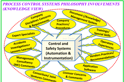
Poppet vs. Spool Valves, Why Valve Type Matters

Contents
PoppetSpool

When selecting 2-Way and 3-Way valves for your pneumatic circuit, be sure to take the internal design of the valve into consideration.  While overall function is the same, the use of a poppet or a spool may have an unexpected impact on your application.  Both of these valve styles, as well as their advantages and disadvantages, are explained below.
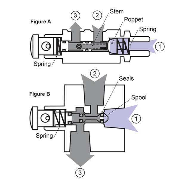
Poppet vs Spool Valves

Poppet

A poppet is a valve component which covers an internal passage and is held in place by air pressure and a spring (Figure A).  Pneumatic 2-Way & 3-Way valves with an internal poppet design require the combination of a spring & air pressure to hold the valve in the unactuated position.  When actuated, a stem pushes the poppet away from the seat to allow air flow.

Advantages

  • The larger internal surface area required by the poppet results in a higher flow rate than spool-style valves
  • Closed crossover – the poppet seals the exhaust port before it opens to flow, therefore, there is no transitional state from one function to the next providing the operator precise control between positions
  • Less wear on internal seals contributes to a longer product life
  • Upon actuation, the port is immediately open to air flow providing faster response times

Disadvantages

  • Poppet valves are unbalanced; pressure must be supplied under the poppet to hold the valve in the unactuated position
  • Typically not recommended for use with vacuum
  • A higher force to actuate is required since both the spring and the air pressure must be overcome to allow air flow
  • Back pressure can open the valve if supply pressure is removed, therefore, poppet valves are not a good choice for holding pressure downstream

Spool

A spool is a valve component which features seals mounted along its surface (Figure B).  When the valve is actuated, the spool shifts causing the seals to travel along the bore, opening ports to allow air flow.

Advantages

  • Spool valves can be used as Selector Valves providing the ability to choose from high and low pressures or vacuum and pressure
  • Spool-style valves are not affected by pressure, therefore, less force is required to actuate the valve
  • Able to be used with vacuum
  • Spool valves are balanced; pressure entering the valve from any given port does not affect the movement of the spool
  • Can be used to lock pressure downstream

Disadvantages

  • Open crossover – all ports are momentarily open to flow as the spool shifts during actuation
  • Lower flow rate than poppet-style valves due to the smaller internal surface area required by the spool
  • Seals mounted on the spool are exposed to wear when traveling through the bore of the valve, shortening product life

Also Read: Solenoid Operated Valves & Latching Valves

Don't Miss Our Updates
Be the first to get exclusive content straight to your email.
We promise not to spam you. You can unsubscribe at any time.
Invalid email address
You've successfully subscribed !

Continue Reading

Multiple Thermowell Installations Problems
Pull Up and Pull Down Switch Circuits
Process Control Systems Philosophy Concept
Switch or Transmitter
Electrical and Instrumentation – Automation Pre-engineering Documents
Major issues for Sensors Selection
Share This Article
Facebook Whatsapp Whatsapp LinkedIn Copy Link
Share
Leave a Comment

Leave a Reply Cancel reply

Your email address will not be published. Required fields are marked *

Stay Connected

128.3kFollowersLike
69.1kFollowersFollow
210kSubscribersSubscribe
38kFollowersFollow

Categories

Explore More

Difference between Intrinsic Safe and Non-Intrinsic Safe Cables
Location of Measurement Displays
All About Variable Area Flow Meters
Instrument Numbering Philosophy
Why is Orifice Beta in between 0.3 to 0.7?
Draw a ladder logic circuit for the electric motor of an air compressor ?
Instrument Junction Box Specification
Immersion Heaters in Lube Oil Consoles

Keep Learning

History of 3-15 psi, 10-50 mA, and 4-20 mA signals

History of 3-15 psi, 10-50 mA, and 4-20 mA signals

Instrumentation Project Documents

List of Instrumentation Project Engineering Documents

Location of Pressure Taps

Design Considerations of Orifice Plate

Instrument Loop Diagram

How-to Create Instrument Loop Diagram (ILD)?

Instrumentation and Control Project Packages

Instrumentation and Control Project Packages – Detail Engineering

Pressure Gauge Maintenance and Troubleshooting

Pressure Gauge Maintenance and Troubleshooting

Determine the statuses of all lamps and relay coils in the circuit

Determine the Status of Lamps and Relays in the Circuit ?

Hammer Effect in Gauges

What is Hammer Effect in Gauges ?

Learn More

Conductive Level Switch Principle

Conductive Level Switch Principle

Spectrometers Questions and Answers

X-Ray Fluorescence Spectrometry Questions and Answers

Electrical Machines Objective Questions

Electrical Machines MCQ Series 3

Compare Solenoid Valve Manual reset and Manual Override

Compare Solenoid Valve Manual Reset and Solenoid Manual Override

Two Wire Sensors Animation

Two Wire Sensor Working Principle and Animation

Convert-Transmitter-Output-in-Percentage-to-Process-Variable

Conversion of Transmitter Output in Percentage to Process Variable

Basic Process Control System

Basic Process Control System

Ion Analyzers Questions and Answers

Special Designs of Ion Selective Electrodes Questions & Answers

Menu

  • About
  • Privacy Policy
  • Copyright

Quick Links

  • Learn PLC
  • Helping Hand
  • Part Time Job

YouTube Subscribe

Follow US
All rights reserved. Reproduction in whole or in part without written permission is prohibited.
Welcome Back!

Sign in to your account

Username or Email Address
Password

Lost your password?