Inst ToolsInst ToolsInst Tools
  • Courses
  • Automation
    • PLC
    • Control System
    • Safety System
    • Communication
    • Fire & Gas System
  • Instrumentation
    • Design
    • Pressure
    • Temperature
    • Flow
    • Level
    • Vibration
    • Analyzer
    • Control Valve
    • Switch
    • Calibration
    • Erection & Commissioning
  • Interview
    • Instrumentation
    • Electrical
    • Electronics
    • Practical
  • Q&A
    • Instrumentation
    • Control System
    • Electrical
    • Electronics
    • Analog Electronics
    • Digital Electronics
    • Power Electronics
    • Microprocessor
  • Request
Search
  • Books
  • Software
  • Projects
  • Process
  • Tools
  • Basics
  • Formula
  • Power Plant
  • Root Cause Analysis
  • Electrical Basics
  • Animation
  • Standards
  • 4-20 mA Course
  • Siemens PLC Course
Reading: Transistor Emitter Bias
Share
Font ResizerAa
Inst ToolsInst Tools
Font ResizerAa
  • Courses
  • Design
  • PLC
  • Interview
  • Control System
Search
  • Courses
  • Automation
    • PLC
    • Control System
    • Safety System
    • Communication
    • Fire & Gas System
  • Instrumentation
    • Design
    • Pressure
    • Temperature
    • Flow
    • Level
    • Vibration
    • Analyzer
    • Control Valve
    • Switch
    • Calibration
    • Erection & Commissioning
  • Interview
    • Instrumentation
    • Electrical
    • Electronics
    • Practical
  • Q&A
    • Instrumentation
    • Control System
    • Electrical
    • Electronics
    • Analog Electronics
    • Digital Electronics
    • Power Electronics
    • Microprocessor
  • Request
Follow US
All rights reserved. Reproduction in whole or in part without written permission is prohibited.
Inst Tools > Blog > Electronic Devices & Circuits > Transistor Emitter Bias

Transistor Emitter Bias

Last updated: September 27, 2016 7:12 am
Editorial Staff
Electronic Devices & Circuits
No Comments
Share
2 Min Read
SHARE

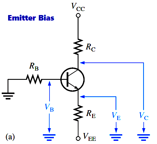
Emitter bias provides excellent bias stability in spite of changes in β or temperature. It uses both a positive and a negative supply voltage. To obtain a reasonable estimate of the key dc values in an emitter-biased circuit, analysis is quite easy. In an npn circuit, such as shown in Figure, the small base current causes the base voltage to be slightly below ground.

The emitter voltage is one diode drop less than this. The combination of this small drop across RB and VBE forces the emitter to be at approximately  -1v. Using this approximation, you can obtain the emitter current as

transistor_emitter-current

VEE is entered as a negative value in this equation.

You can apply the approximation that IC = IE to calculate the collector voltage.

VC = VCC – ICRC

The approximation that VE = -1v is useful for troubleshooting because you won’t need to perform any detailed calculations. As in the case of voltage-divider bias, there is a more rigorous calculation for cases where you need a more exact result.

transistor-emitter-bias

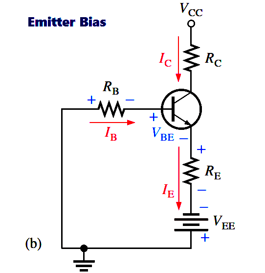
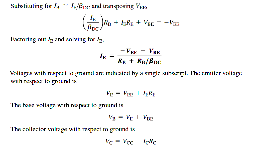
The approximation that VE = -1v and the neglect of βDC may not be accurate enough for design work or detailed analysis. In this case, Kirchhoff’s voltage law can be applied as follows to develop a more detailed formula for IE. Kirchhoff’s voltage law applied around the base-emitter circuit in Figure (a), which has been redrawn in part (b) for analysis, gives the following equation:

transistor-emitter-bias-principle

VEE + VRB + VBE + VRE = 0

Substituting, using Ohm’s law,

VEE + IBRB + VBE + IERE = 0

transistor-emitter-bias-derivation


Don't Miss Our Updates
Be the first to get exclusive content straight to your email.
We promise not to spam you. You can unsubscribe at any time.
Invalid email address
You've successfully subscribed !

Continue Reading

Resistors Principle & Applications
Electron Gun of Cathode Ray Tube
Short Notes on Rectifiers & Filters
Transistor Collector Feedback Bias
JFET Working Animation
Optocouplers Working Principle
Share This Article
Facebook Whatsapp Whatsapp LinkedIn Copy Link
Share
Leave a Comment

Leave a Reply Cancel reply

Your email address will not be published. Required fields are marked *

Stay Connected

128.3kFollowersLike
69.1kFollowersFollow
210kSubscribersSubscribe
38kFollowersFollow

Categories

Explore More

Basic DC Power Supply Circuit
Peak Inverse Voltage of Center Tap Rectifier
Varactor Diode Operation
What is a Filter Circuit ?
Transistor Collector Characteristic Curves
Difference between Schottky Diode and PN junction Diode
Diode Limiters/Clippers Operation
Half Wave Rectifier Principle

Keep Learning

How a Multi Color LED Works

How a Multi Color LED Works ?

Derivation-of-Ohms-Law

Basics of Ohm’s Law

schottky diode working principle

Schottky Diode Working Principle

Basics of Amplifiers Interview Questions

Amplifiers Questions & Answers

zener-diode-as-voltage-regulator

Operation of Zener Diode Voltage Regulator

Testing a defective transistor

Testing a Transistor with a Digital Multimeter

Optoisolator Working Principle

Optoisolator Working Principle

transistor-biasing-circuits

Summary Of Transistor Bias Circuits

Learn More

Marking Polarity

DC Circuit Analysis Loop Equations

Open Tank Level Measurement using DP Transmitter

Open Tank Level Measurement using DP Transmitter

annunciator-alarm-simulator

Alarm Simulator for Annunciator Logic

Why Grounding

Generating Station Grounding Principles

Ohms Law Equation

Ohms Law Calculator

What happen When Synchronous Generator loss Excitation

Video Borescope

5 Questions to Ask Before Choosing Your Industrial Borescope

Valve-Kv-Sizing-Calculator

Valve Kv Sizing Calculator

Menu

  • About
  • Privacy Policy
  • Copyright

Quick Links

  • Learn PLC
  • Helping Hand
  • Part Time Job

YouTube Subscribe

Follow US
All rights reserved. Reproduction in whole or in part without written permission is prohibited.
Welcome Back!

Sign in to your account

Username or Email Address
Password

Lost your password?