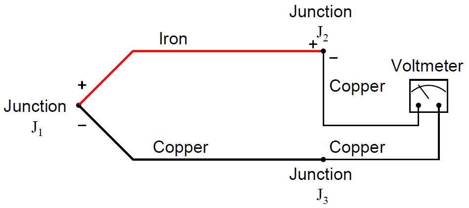
It is crucial to realize that the phenomenon of a “reference junction” is an inevitable effect of having to close the electric circuit loop in a circuit made of dissimilar metals.
This is true regardless of the number of metals involved. In the last example, only two metals were involved: iron and copper. This formed one iron-copper junction (J1) at the measurement end and one iron-copper junction (J2) at the indicator end.
Recall that the copper-copper junction J3 was of no consequence because its identical metallic composition generates no thermal voltage:
But what about more complex thermocouple circuits, involving more than two wire types? How do we define what a “reference junction” is, or how it behaves, when we have more than two dissimilar-metal junctions in the same circuit? Take for instance this example of a type J thermocouple:
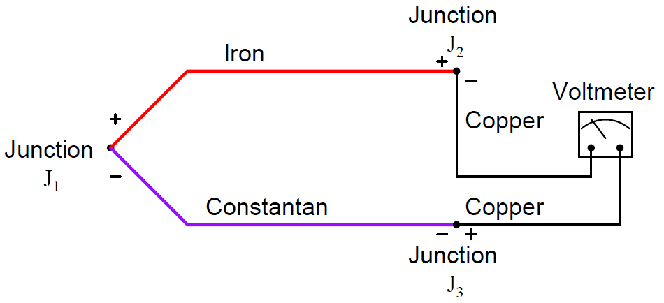
Here we have three voltage-generating junctions: J1 of iron and constantan, J2 of iron and copper, and J3 of copper and constantan.
Upon first inspection it would seem we have a much more complex situation than we did with just two metals (iron and copper), but fortunately the situation is just as simple as it was before provided the temperatures of J2 and J3 are equal, which will be true if those two junctions are located very near each other (at the voltmeter).
Note : A junction of copper and constantan just happens to be a type T thermocouple junction.
A principle of thermo-electric circuits called the Law of Intermediate Metals helps us see this clearly.
According to this law, intermediate metals in a series of junctions are of no consequence to the overall (net) voltage so long as those intermediate junctions are all at the same temperature.
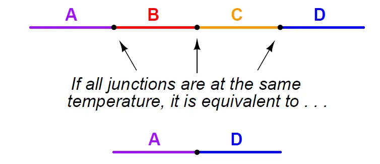
Representing this pictorially, the net effect of having four different metals (A, B, C, and D) joined together in series is the same as just having the first and last metal in that series (A and D) joined with one junction, if all intermediate junctions are at the same temperature:
A simple proof of the Law of Intermediate Metals may be built upon the Law of Energy Conservation, one of the most fundamental principles in all of physics.
Consider what would happen if we were to join the series of dissimilar metal wires shown above into a continuous loop:
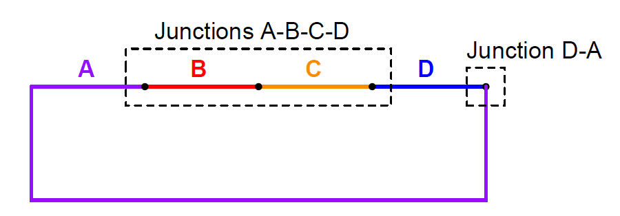
In this diagram we see that the wire made of metal “A” connects to a string of metal junctions formed by metals “B”, “C”, and “D”.
If all these dissimilar metal junctions are at the same temperature, there will be no difference of temperature anywhere in the circuit to drive a current, and we would therefore expect the current in this circuit to be zero.
This is in accordance with the Law of Energy Conservation, which forbids the passage of electric current through resistive wire without some motive power source driving it. Thus, based on the premise that energy must be conserved (i.e. that an electric current cannot flow through any resistance without a power source), we must conclude that the net effect of all those series-connected metal junctions at the same temperature must be zero.
In other words, junctions A-B, B-C, C-D, and D-A all at the same temperature and connected in series must generate zero voltage, as if those junctions were all reduced to a single A-A junction which of course cannot produce any electromotive force (voltage) because it is not comprised of dissimilar metals.
If the Law of Intermediate Metals were untrue, it would mean that the junctions A-B-C-D were not equivalent to the single junction A-D, which would mean they would produce a different voltage than the D-A junction at the right-hand end of this circuit (while at the same temperature), and therefore this circuit would produce some net voltage to drive a current continuously through resistive wire in violation of the Law of Energy Conservation.
Since we know the Law of Energy Conservation to be well-founded (and we can also build such dissimilar metal loop circuits and empirically determine their currents to be zero), we may rest assured that the Law of Intermediate Metals is true.
In our type J thermocouple circuit where iron and constantan both join to copper, we see copper as an intermediate metal between junctions J2 and J3. Being located next to each other on the indicating instrument, identical temperature is a reasonable assumption for J2 and J3, so we may invoke the Law of Intermediate Metals and simply treat junctions J2 and J3 as a single iron-constantan reference junction.
In other words, the Law of Intermediate Metals tells us we can treat the following two circuits identically:
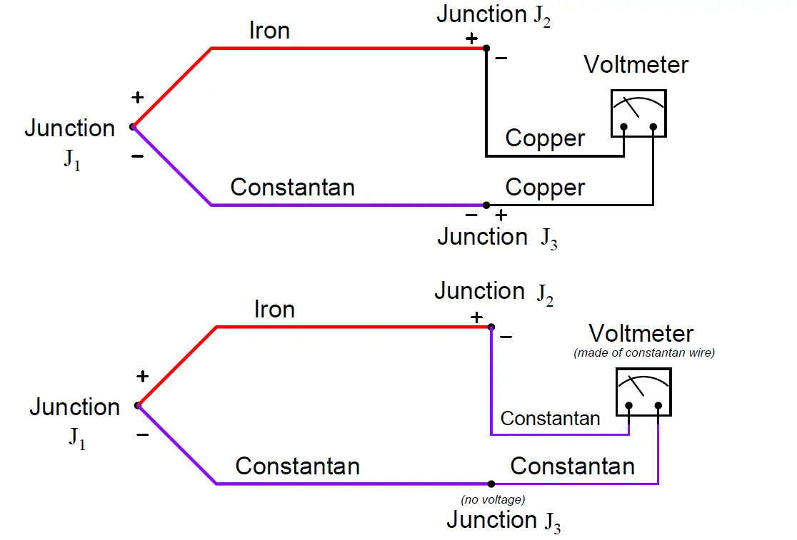
The practical importance of this Law is that we can always treat the reference junction(s) as a single junction made from the same two metal types as the measurement junction, so long as all dissimilar metal junctions at the reference location are at the same temperature.
This fact is extremely important in the age of semiconductor circuitry, where the connection of a thermocouple to an electronic amplifier involves a long series of dissimilar-material junctions.
Here we see a multitude of reference junctions, formed by the necessary connections from thermocouple wire to the silicon substrate inside the amplifier chip:
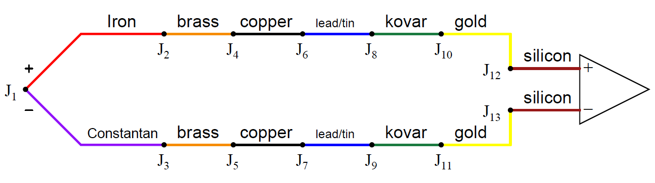
Here we see the metals of the thermocouple wire (type J – iron and constantan) joining to a pair of brass terminal screws, which in turn join to copper traces on a printed circuit board, which join to lead/tin solder, which join to thin wires made of Kovar, which terminate at gold traces on the silicon chip, which are bonded to the silicon itself.
It should be obvious that each complementary junction pair in this series loop cancel each other if each pair is at the same temperature (e.g. gold-silicon junction J12 cancels with silicon-gold junction J13 because they generate the exact same amount of voltage with opposing polarities;
Kovar-gold junction J10 cancels with gold-Kovar junction J11 for the same reason; etc.).
The Law of Intermediate Metals goes one step further by telling us junctions J2 through J13 taken together in series are of the same effect as a single reference junction of iron and constantan.
Automatic reference junction compensation is as simple as counter-acting the voltage produced by this equivalent iron-constantan junction at whatever temperature junctions J2 through J13 happen to be at.
Also Read : Laws of Thermocouples
Credits : Tony R. Kuphaldt – Creative Commons Attribution 4.0 License