Hydrostatic pressure sensors may be used to detect the level of a liquid-liquid interface, if and only if the total height of liquid never drops down into the sensing range of the interface level instrument. This is critically important because any single hydrostatic-based level instrument cannot discriminate between a changing interface level and a changing total level within the same range, and therefore the latter must be fixed in order to measure the former.
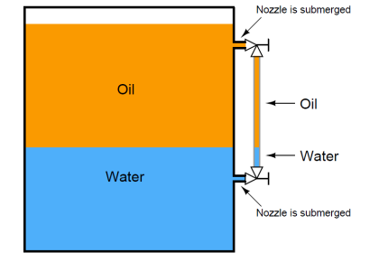
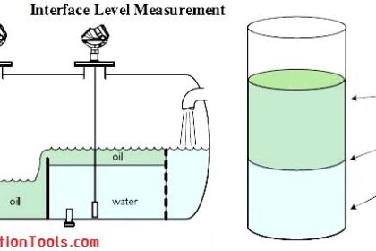
One way to ensure this condition is to fix the total liquid height to some constant value by using an overflow pipe, and ensuring drain flow is always less than incoming flow (forcing some flow to always go through the overflow pipe). This strategy naturally lends itself to separation processes, where a mixture of light and heavy liquids are separated by their differing densities:
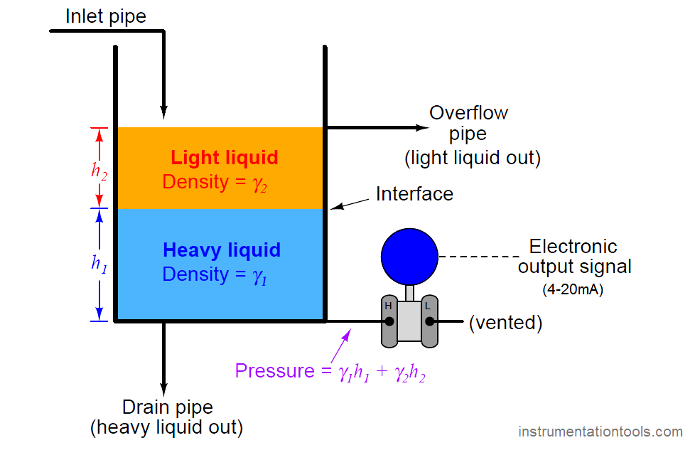
Here we see a practical application for liquid-liquid interface level measurement. If the goal is to separate two liquids of differing densities from one another, we need only the light liquid to exit out the overflow pipe and only the heavy liquid to exit out the drain pipe. This means we must control the interface level to stay between those two piping points on the vessel. If the interface drifts too far up, heavy liquid will be carried out the overflow pipe; and if we let the interface drift too far down, light liquid will flow out of the drain pipe. The first step in controlling any process variable is to measure that variable, and so here we are faced with the necessity of measuring the interface point between the light and heavy liquids.
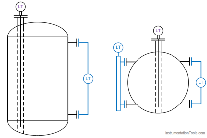
Another way to address the problem of varying total liquid height is to use a compensating leg located at a point on the vessel below the total liquid height. In this example, a transmitter with remote seals is used:
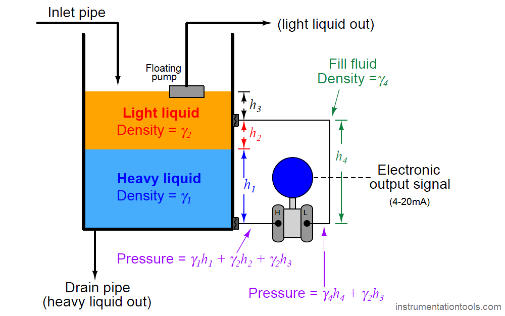
Since both sides of the differential pressure transmitter “see” the hydrostatic pressure generated by the liquid column above the top connection point (γ2h3), this term naturally cancels. The result of this is that total liquid height becomes irrelevant, so long as it remains above the upper connection point:
(γ1h1 + γ2h2 + γ2h3) − (γ4h4 + γ2h3)
γ1h1 + γ2h2 + γ2h3 − γ4h4 − γ2h3
γ1h1 + γ2h2 − γ4h4
The hydrostatic pressure in the compensating leg is constant (γ4h4 = Constant), since the fill fluid never changes density and the compensating leg’s height never changes. This means the transmitter’s sensed pressure will differ from that of an uncompensated transmitter merely by a constant offset, which may be “calibrated out” so as to have no impact on the measurement:
γ1h1 + γ2h2 − Constant
At first, it may seem as though determining the calibration points (lower- and upper-range values: LRV and URV) for a hydrostatic interface level transmitter is impossibly daunting given all the different pressures involved. A recommended problem-solving technique to apply here is that of a thought experiment, where we imagine what the process will “look like” at lower-range value condition and at the upper-range value condition, drawing two separate illustrations:
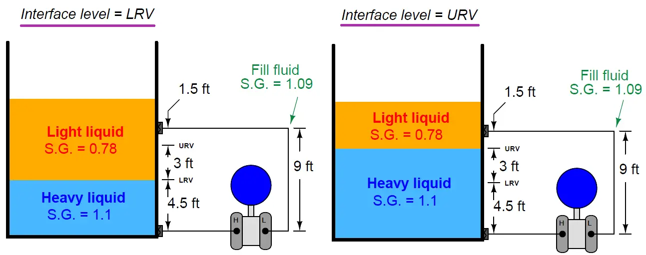
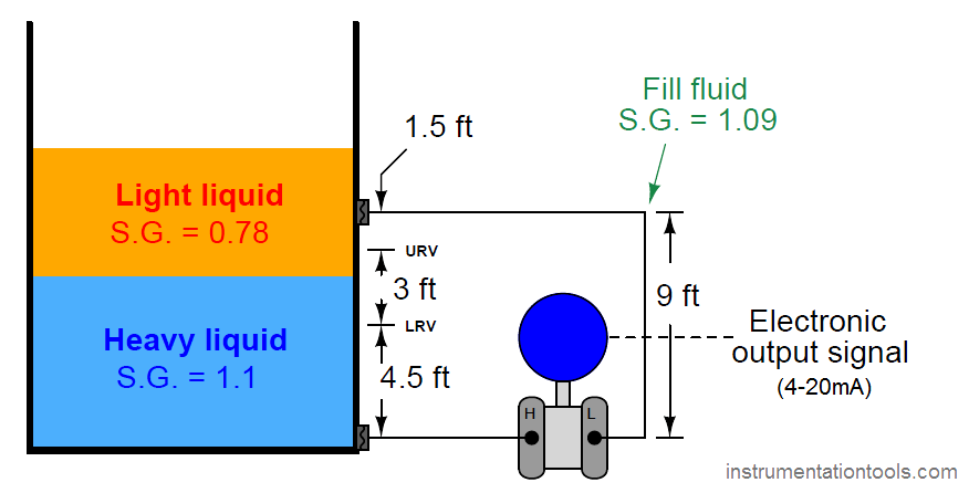
For example, suppose we must calibrate a differential pressure transmitter to measure the interface level between two liquids having specific gravities of 1.1 and 0.78, respectively, over a span of 3 feet. The transmitter is equipped with remote seals, each containing a halocarbon fill fluid with a specific gravity of 1.09. The physical layout of the system is as follows:
As the first step in our “thought experiment,” we imagine what the process would look like with the interface at the LRV level, calculating hydrostatic pressures seen at each side of the transmitter. For this I recommend actually sketching a simple diagram showing what the fluid levels would look like with the interface at the LRV point, so the height dimensions of each liquid layer become obvious:
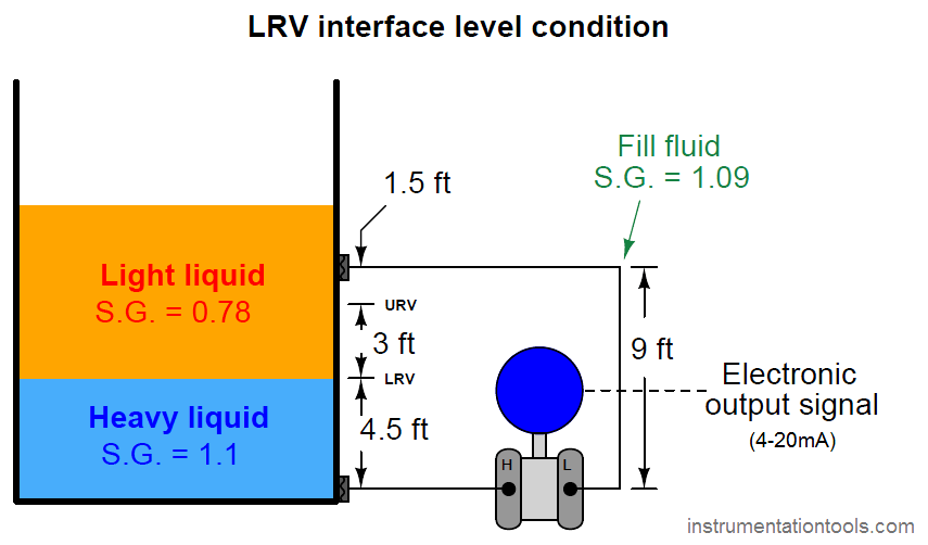
We know from our previous exploration of this setup that any hydrostatic pressure resulting from liquid level above the top remote seal location is irrelevant to the transmitter, since it is “seen” on both sides of the transmitter and thus cancels out. All we must do, then, is calculate hydrostatic pressures as though the total liquid level stopped at that upper diaphragm connection point.
First, calculating the hydrostatic pressure “seen” at the high port of the transmitter :
Phigh = 4.5 feet of heavy liquid + 4.5 feet of light liquid
Phigh = 54 inches of heavy liquid + 54 inches of light liquid
Phigh ”W.C. = (54 inches of heavy liquid)(1.1) + (54 inches of light liquid)(0.78)
Phigh ”W.C. = 59.4 ”W.C. + 42.12 ”W.C.
Phigh = 101.52 ”W.C.
Next, calculating the hydrostatic pressure “seen” at the low port of the transmitter:
Plow = 9 feet of fill fluid
Plow = 108 inches of fill fluid
Plow ”W.C. = (108 inches of fill fluid)(1.09)
Plow = 117.72 ”W.C.
The differential pressure applied to the transmitter in this condition is the difference between the high and low port pressures, which becomes the lower range value (LRV) for calibration:
PLRV = 101.52 ”W.C. − 117.72 ”W.C. = −16.2 ”W.C.
As the second step in our “thought experiment,” we imagine what the process would look like with the interface at the URV level, calculating hydrostatic pressures seen at each side of the transmitter. Again, sketching a simple diagram of what the liquid layers would look like in this condition helps us visualize the scenario:
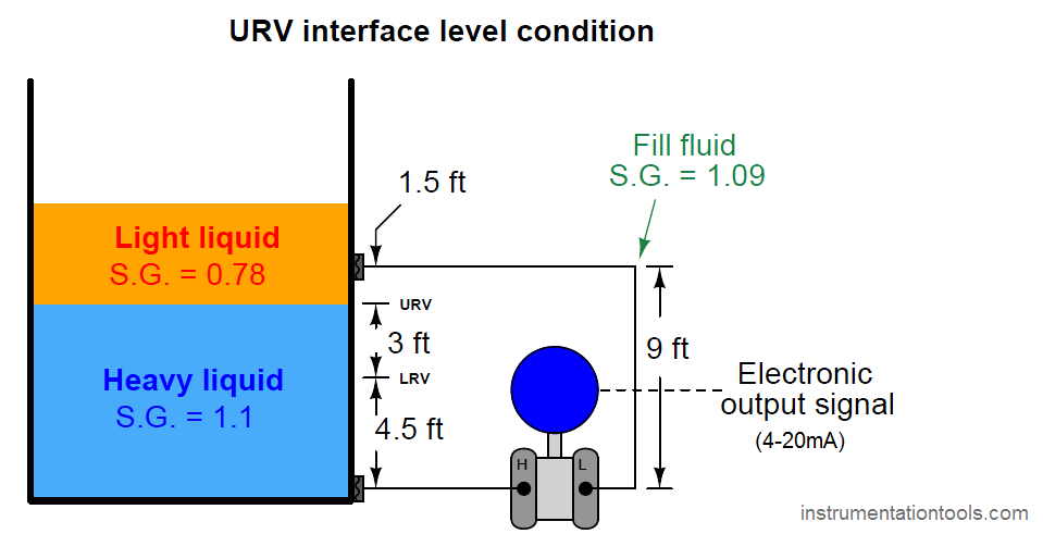
Phigh = 7.5 feet of heavy liquid + 1.5 feet of light liquid
Phigh = 90 inches of heavy liquid + 18 inches of light liquid
Phigh ”W.C. = (90 inches of heavy liquid)(1.1) + (18 inches of light liquid)(0.78)
Phigh ”W.C. = 99 ”W.C. + 14.04 ”W.C.
Phigh = 113.04 ”W.C.
The hydrostatic pressure of the compensating leg is exactly the same as it was before: 9 feet of fill fluid having a specific gravity of 1.09, which means there is no need to calculate it again. It will still be 117.72 inches of water column. Thus, the differential pressure at the URV point is:
PURV = 113.04 ”W.C. − 117.72 ”W.C. = −4.68 ”W.C.
Using these two pressure values and some interpolation, we may generate a 5-point calibration table (assuming a 4-20 mA transmitter output signal range) for this interface level measurement system:
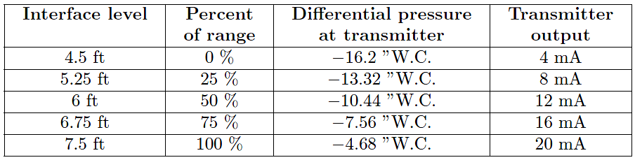
When the time comes to bench-calibrate this instrument in the shop, the easiest way to do so will be to set the two remote diaphragms on the workbench (at the same level), then apply 16.2 to 4.68 inches of water column pressure to the low remote seal diaphragm with the other diaphragm at atmospheric pressure to simulate the desired range of negative differential pressures.
The more mathematically inclined reader will notice that the span of this instrument (Span = URV − LRV) is equal to the span of the interface level (3 feet, or 36 inches) multiplied by the difference in specific gravities (1.1 − 0.78):
Span in ”W.C. = (36 inches)(1.1 − 0.78)
Span = 11.52 ”W.C.
Looking at our two “thought experiment” illustrations, we see that the only difference between the two scenarios is the type of liquid filling that 3-foot region between the LRV and URV marks. Therefore, the only difference between the transmitter’s pressures in those two conditions will be the difference in height multiplied by the difference in density. Not only is this an easy way for us to quickly calculate the necessary transmitter span, but it also is a way for us to check our previous work: we see that the difference between the LRV and URV pressures is indeed a difference of 11.52 inches water column just as this method predicts.
Credits : Tony R. Kuphaldt – Creative Commons Attribution 4.0 License


Dear sir,
How did you got value of Interface level?
because in one of your article of finding interface level of the tank u have mentioned one formula
that Interface(i)=(DP-LRV)*L/SPAN ,
but it is not applicable here as per the calculation so can u just clarify this?
Sir, How can we know the level of Interface , because in one of your article u have mentioned formula that Interface level(I)=(DP-LRV)L/Span.
And this formula is not solving above example,so can u please give us some idea that how u found that and when can we use this formula?