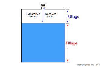
Level Gauge Interface Problems
As simple and apparently trouble-free as level gauges may seem, there are special circumstances where they will register incorrectly.
One such circumstance is in the presence of a lighter liquid layer existing between the connection ports of the gauge.
If a lighter (less dense) liquid exists above a heavier (denser) liquid in the process vessel, the level gauge may not show the proper interface, if at all:
A practical application of level measurement where two liquids form an interface is where water exists in the presence of petroleum substances, such as diesel fuel.
Water is a denser liquid than most oils, and these two liquids are immiscible, which means the denser water forms a separate layer beneath the lighter oil.
Another application of interface measurement is in the oil and gas extraction industry, where water must be separated from petroleum fluids coming out of wells drilled deep into the earth.
Fluid from an oil well enters a special vessel called a “separator” where gravity causes the water to separate from the petroleum liquids, and petroleum vapors to separate from all liquids.
These water/oil/gas separator vessels are critical components of any petroleum well system, with the liquid-liquid interface between water and oil being an important process variable to measure and control.
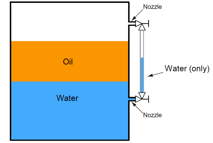
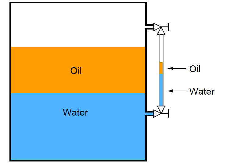
In the above illustration we see how a column of water in the sightglass shows less (total) level than the combination of water and oil inside a process vessel.
Since the oil lies between the two level gauge ports into the vessel (sometimes called nozzles), it cannot enter the sightglass tube, and therefore the level gauge will continue to show just water.
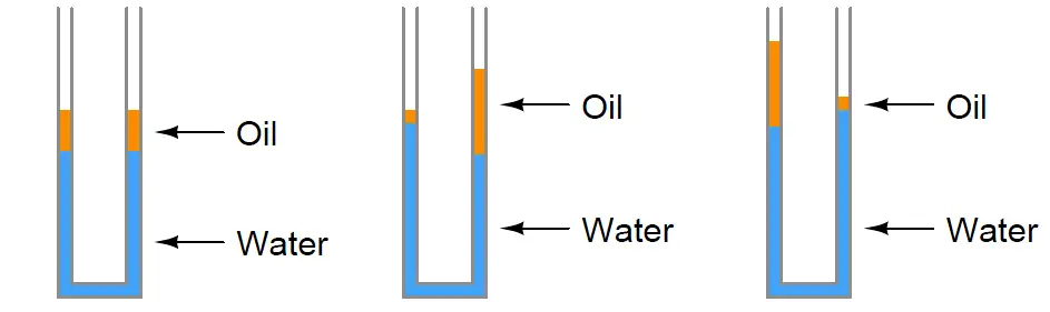
If by chance some oil does find its way into the sightglass tube – either by the interface level dropping below the lower nozzle or the total level rising above the upper nozzle – the oil/water interface shown inside the level gauge may not continue to reflect the true interface inside the vessel once the interface and total levels return to their previous positions:
Recall that the level gauge and vessel together form a U-tube manometer. So long as the pressures from each liquid column are the same, the columns balance each other.
The problem is, many different liquid-liquid interface columns can have the same hydrostatic pressure without being identical to one another:
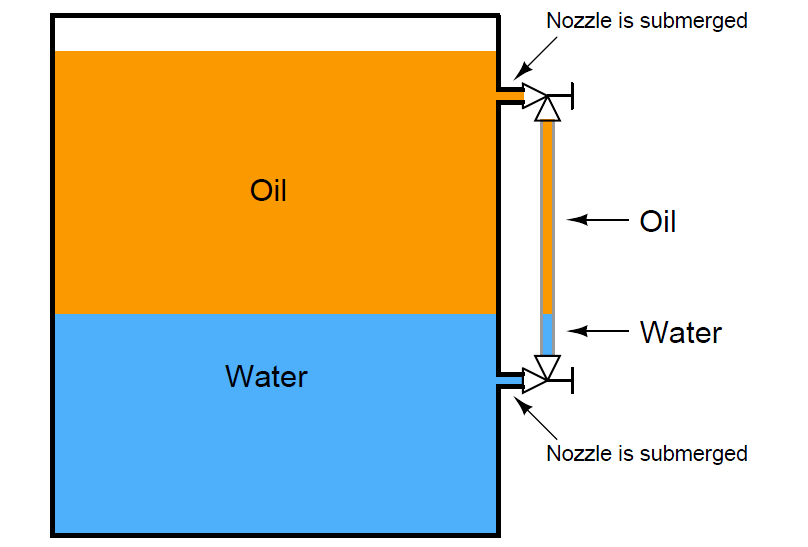
The only way to ensure proper two-part liquid interface level indication in a sightglass is to keep both ports (nozzles) submerged:
Level Gauge Temperature Problems
Another troublesome scenario for level gauges is when the liquid inside the vessel is substantially hotter than the liquid in the gauge, causing the densities to be different.
This is commonly seen on boiler level gauges, where the water inside the sightglass cools off substantially from its former temperature inside the boiler drum:
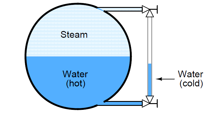
Looking at the sightglass as a U-tube manometer again, we see that unequal-height liquid columns may indeed balance each other’s hydrostatic pressures if the two columns are comprised of liquids with different densities.
The weight density of water is 62.4 lb/ft3 at standard temperature, but may be as low as only 36 lb/ft3 at temperatures common for power generation boilers.
Credits : Tony R. Kuphaldt – Creative Commons Attribution 4.0 License