Inst ToolsInst ToolsInst Tools
  • Courses
  • Videos
  • Q & A
    • Interview
      • Instrumentation
      • Electronics
      • Electrical
      • Practical Questions
    • MCQ
      • Instrumentation MCQ
      • Electrical MCQ
      • Electronics MCQ
      • Control Systems MCQ
      • Analog Electronics MCQ
      • Digital Electronics MCQ
      • Power Electronics MCQ
      • Microprocessor MCQ
      • Multiple Choice Questions
  • EE
    • Electronics
      • Electronics Q & A
      • Electronic Basics
      • Electronic Devices & Circuits
      • Electronics Animation
      • Digital Electronics
    • Electrical
      • Electrical Basics
      • Electrical Q & A
      • Power Electronics
      • Electrical Machines
      • Electrical Animation
      • Power Systems
      • Switchgear & Protection
      • Transmission & Distribution
  • Measure
    • Control Valves
    • Calibration
    • Temperature
    • Pressure
    • Flow
    • Level
    • Analyzers
    • Switches
    • Vibration
    • Solenoid Valve
  • Control
    • PLC Tutorials
    • Control Systems
    • Safety Instrumented System (SIS)
    • Communication
    • Fire & Gas System
  • More
    • Design
    • Tools
    • Animation
    • Basics
    • Formulas
    • Standards
    • TextBooks
    • Common
    • Software
    • Excel Tools
    • Erection & Commissioning
    • Process Fundamentals
    • Videos
    • Books
Search
All rights reserved. Reproduction in whole or in part without written permission is prohibited.
Reading: Pressure Transmitter Vent fittings
Share
Notification Show More
Font ResizerAa
Inst ToolsInst Tools
Font ResizerAa
  • Courses
  • PLC Tutorials
  • Control Systems
Search
  • Courses
  • Videos
  • Q & A
    • Interview
    • MCQ
  • EE
    • Electronics
    • Electrical
  • Measure
    • Control Valves
    • Calibration
    • Temperature
    • Pressure
    • Flow
    • Level
    • Analyzers
    • Switches
    • Vibration
    • Solenoid Valve
  • Control
    • PLC Tutorials
    • Control Systems
    • Safety Instrumented System (SIS)
    • Communication
    • Fire & Gas System
  • More
    • Design
    • Tools
    • Animation
    • Basics
    • Formulas
    • Standards
    • TextBooks
    • Common
    • Software
    • Excel Tools
    • Erection & Commissioning
    • Process Fundamentals
    • Videos
    • Books
Follow US
All rights reserved. Reproduction in whole or in part without written permission is prohibited.
Inst Tools > Blog > Erection & Commissioning > Pressure Transmitter Vent fittings

Pressure Transmitter Vent fittings

Last updated: January 14, 2019 9:08 pm
Editorial Staff
Erection & Commissioning Pressure Measurement
No Comments
Share
5 Min Read
SHARE

Before removing a pressure transmitter from live service, the technician must “bleed” or “vent” accumulated fluid pressure to atmosphere in order to achieve a zero energy state prior to disconnecting the transmitter from the impulse lines. Some valve manifolds provide a bleed valve for doing just this, but many do not. An inexpensive and common accessory for pressure-sensing instruments (especially transmitters) is the bleed valve fitting or vent valve fitting, installed on the instrument as a discrete device.

The most common bleed fitting is equipped with 1/4 inch male NPT pipe threads, for installation into one of the 1/4 inch female NPT pipe ports typically provided on pressure transmitter flanges. The bleed fitting is operated with a small wrench, loosening a ball-tipped plug off its seat to allow process fluid to escape through a small vent hole in the side of the fitting.

The following photographs show close-up views of a bleed fitting both assembled (left) and with the plug fully extracted from the fitting (right). The bleed hole may be clearly seen in both photographs:

Pressure Transmitter Vent Fittings

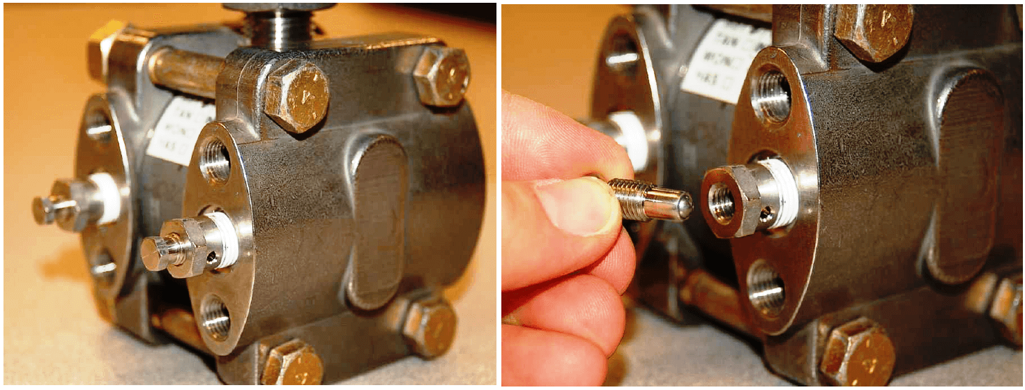
When installed directly on the flanges of a pressure instrument, these bleed valves may be used to bleed unwanted fluids from the pressure chambers, for example bleeding air bubbles from an instrument intended to sense water pressure, or bleeding condensed water out of an instrument intended to sense compressed air pressure.

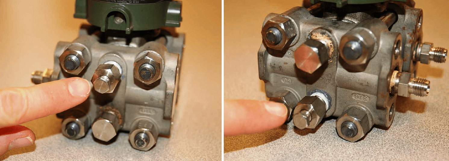
The following photographs show bleed fittings installed two different ways on the side of a pressure transmitter flange, one way to bleed gas out of a liquid process (located on top) and the other way to bleed liquid out of a gas process (located on bottom):

Pressure Transmitter Fittings

NOTE : The standard 3-valve manifold, for instance, does not provide a bleed valve – only block and equalizing valves.

With the bleed plug completely removed, the open bleed fitting provides a port through which one may apply air pressure for testing the response of the pressure transmitter. A special test fitting called a bleed port adapter or DP transmitter calibration fitting – colloquially known as a stinger – threads into the opened bleed fitting.

A photograph of a bleed port adapter is shown here:

Pressure Transmitter bleed port adapter

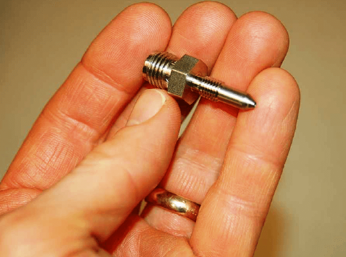
This special fitting allows a compression-style tube to be temporarily connected to the opened bleed port, which then allows the connection of an air pump and test pressure gauge to the transmitter. Thus, the bleed port adapter enables a technician to conveniently apply test pressures to the DP transmitter without having to loosen any of the instrument manifold bolts, tapered thread pipe connections, or impulse tube compression fittings.

When performing field checks of pressure transmitters, bleed port adapters substantially reduce the amount of time necessary to field-test pressure instruments. The following sequence of illustrations show how a bleed port adapter may be used in conjunction with a three-valve instrument manifold to isolate a DP transmitter from a process and then subject it to test pressures from a hand pump:

pressure transmitters bleed port

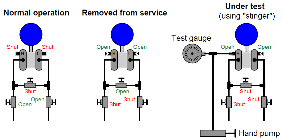
Note how both bleed vents must be opened, and the equalizing valve shut, in order to apply a test pressure to the DP transmitter.

Although it is possible to safely bleed pressure from both sides of a DP instrument through just one bleed fitting (through the open equalizing valve), both bleeds must be open in order to perform a pressure test. If the “L” side bleed fitting is left in the shut position, some pressure may be trapped there as pressure is applied to the “H” side by the hand pump. If the equalizing valve is left open, no difference of pressure will be allowed to form across the DP instrument.

 Credits : Tony R. Kuphaldt – Creative Commons Attribution 4.0 License

Don't Miss Our Updates
Be the first to get exclusive content straight to your email.
We promise not to spam you. You can unsubscribe at any time.
Invalid email address
You've successfully subscribed !

Recommended Articles

Impulse Line Purging and Close Coupling of Instruments
Difference Between Absolute and Gauge Pressure
Top 30 Interview Questions on Pressure Measuring Devices
Pressure Gauge Installation at Pump Discharge
Differential Pressure Transmitter with 5 Way Manifold Valve
Basics of Pressure switches
Share This Article
Facebook Whatsapp Whatsapp LinkedIn Copy Link
Share
Leave a Comment

Leave a Reply Cancel reply

Your email address will not be published. Required fields are marked *

Stay Connected

128.3kFollowersLike
69.1kFollowersFollow
208kSubscribersSubscribe
38kFollowersFollow

Categories

Recent Comments

  • William Snyder on Top Non-PLC Certification Courses for Automation Professionals
  • Kamli on Top Free PLC Software
  • Guifty Shimica on Top Non-PLC Certification Courses for Automation Professionals
  • Guifty Shimica on Top Non-PLC Certification Courses for Automation Professionals

Related Articles

Impulse line - Purpose & Tapping Point Location

Impulse Line – Purpose & Tapping Point Location

Pressure Gauge Water traps and pigtail siphons

Pressure Gauge Water Traps and Pigtail Siphons

Installation and Calibration of Pressure Transmitter

Installation and Calibration of Pressure Transmitter

Compression load cell Principle

Types of Load Cells

Triangle A-B-C- with Arc “A-C”

Instrument Tube Fitting Installation – Part 2

Thermocouple Temperature Measurements Errors

Thermocouple Temperature Measurement Errors

Linear Variable Displacement Transducer (LVDT)

What is LVDT ?

Cut-outs between Platforms or Grating for Field Instruments

Cut-outs between Platforms or Grating for Field Instruments

More Articles

Power Electronics Objective Questions

Current Source Inverters Objective Questions

Dry Leg

Calculate 0%, 50%, and 100% Calibration Points for ΔP transmitter

Digital Electronics Multiple Choice Questions

Programmable Read Only Memory Objective Questions – Part 1

Example PLC Program to Control a Pump based on Level Sensors

Example PLC Program to Control a Pump based on Level Sensors

Industrial Internet of Things Projects

Top 100 Industrial Internet of Things Projects (IIoT)

Performance of Systems Objective Questions

Performance of Control Systems Objective Questions

Digital Electronics Multiple Choice Questions

Memory Devices Objective Questions – Part 4

How to Find the Correct Solenoid Valve Size

How to Find the Correct Solenoid Valve Size?

Follow US
All rights reserved. Reproduction in whole or in part without written permission is prohibited.
Welcome Back!

Sign in to your account

Username or Email Address
Password

Lost your password?