Inst ToolsInst ToolsInst Tools
  • Ask
  • Courses
  • Videos
  • Q & A
    • Interview
      • Instrumentation
      • Electronics
      • Electrical
      • Practical Questions
    • MCQ
      • Instrumentation MCQ
      • Electrical MCQ
      • Electronics MCQ
      • Control Systems MCQ
      • Analog Electronics MCQ
      • Digital Electronics MCQ
      • Power Electronics MCQ
      • Microprocessor MCQ
      • Multiple Choice Questions
  • EE
    • Electronics
      • Electronics Q & A
      • Electronic Basics
      • Electronic Devices & Circuits
      • Electronics Animation
      • Digital Electronics
    • Electrical
      • Electrical Basics
      • Electrical Q & A
      • Power Electronics
      • Electrical Machines
      • Electrical Animation
      • Power Systems
      • Switchgear & Protection
      • Transmission & Distribution
  • Measure
    • Control Valves
    • Calibration
    • Temperature
    • Pressure
    • Flow
    • Level
    • Analyzers
    • Switches
    • Vibration
    • Solenoid Valve
  • Control
    • PLC Tutorials
    • Control Systems
    • Safety Instrumented System (SIS)
    • Communication
    • Fire & Gas System
  • More
    • Design
    • Tools
    • Animation
    • Basics
    • Formulas
    • Standards
    • TextBooks
    • Common
    • Software
    • Excel Tools
    • Erection & Commissioning
    • Process Fundamentals
    • Videos
    • Books
Search
All rights reserved. Reproduction in whole or in part without written permission is prohibited.
Reading: Programmable Logic Controller (PLC) Questions and Answers – 11
Share
Notification Show More
Font ResizerAa
Inst ToolsInst Tools
Font ResizerAa
  • Courses
  • PLC Tutorials
  • Control Systems
Search
  • Ask
  • Courses
  • Videos
  • Q & A
    • Interview
    • MCQ
  • EE
    • Electronics
    • Electrical
  • Measure
    • Control Valves
    • Calibration
    • Temperature
    • Pressure
    • Flow
    • Level
    • Analyzers
    • Switches
    • Vibration
    • Solenoid Valve
  • Control
    • PLC Tutorials
    • Control Systems
    • Safety Instrumented System (SIS)
    • Communication
    • Fire & Gas System
  • More
    • Design
    • Tools
    • Animation
    • Basics
    • Formulas
    • Standards
    • TextBooks
    • Common
    • Software
    • Excel Tools
    • Erection & Commissioning
    • Process Fundamentals
    • Videos
    • Books
Follow US
All rights reserved. Reproduction in whole or in part without written permission is prohibited.
Inst Tools > Blog > Practical Questions > Programmable Logic Controller (PLC) Questions and Answers – 11

Programmable Logic Controller (PLC) Questions and Answers – 11

Last updated: September 24, 2018 7:34 am
Editorial Staff
Practical Questions
2 Comments
Share
1 Min Read
SHARE

Programmable Logic Controller (PLC) Questions 

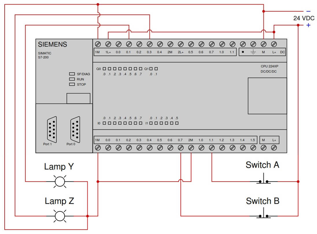
Suppose we have a Siemens S7-200 PLC connected to a pair of pushbutton switches and light bulbs as shown in this illustration:

Siemens PLC Questions

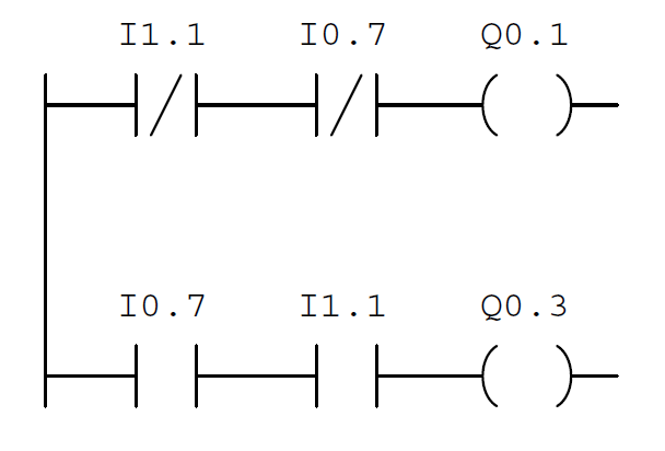
Examine the following relay ladder logic (RLL) program for this Siemens PLC, determining the statuses of the two lamps provided neither switch is pressed by a human operator:

Siemens S7-200 PLC Ladder Logic for Switch - 2

Furthermore, determine the necessary switch actuation statuses (i.e. pressed versus unpressed) to turn lamp Z on.

Answer :

Output Q0.1 will activate to energize lamp Y, but the other output (and lamp) will remain off.

To energize lamp Z, you must release (unpress) both switches.

Share Your Answer / Comments

Credits :  Tony R. Kuphaldt – under CC BY 1.0

For More PLC Questions : CLICK HERE


Don't Miss Our Updates
Be the first to get exclusive content straight to your email.
We promise not to spam you. You can unsubscribe at any time.
Invalid email address
You've successfully subscribed !
Practical Process Control System Questions & Answers – 11
Loop Powered Pressure Transmitter
Purpose of Stop in a Pressure Measuring Instrument
Diagnosing Electric Motor Circuit
Calculate Incident Power in Radar Level Measurement
Share This Article
Facebook Whatsapp Whatsapp LinkedIn Copy Link
Share
2 Comments
  • azetou says:
    August 30, 2017 at 1:17 pm

    I think that there is a mistake in your answer:

    If neither switches are pressed, it means both of theme are conducting (they are normally closed switches) it means I.11 and I.07 are both at state “1”, but in the program in the first rung, the contacts are negated it means that Q0.1 will be de-energized = lamp Y is “off”.

    Reply
  • chuangbing chen says:
    March 30, 2021 at 9:25 am

    I agree with azetou.

    Reply

Leave a Reply Cancel reply

Your email address will not be published. Required fields are marked *

Stay Connected

128.3kFollowersLike
69.1kFollowersFollow
208kSubscribersSubscribe
38kFollowersFollow

Categories

Recent Comments

  • Kamli on Top Free PLC Software
  • Guifty Shimica on Top Non-PLC Certification Courses for Automation Professionals
  • Guifty Shimica on Top Non-PLC Certification Courses for Automation Professionals
  • MIHARITSOA Aina Sitraka on Top Non-PLC Certification Courses for Automation Professionals

Related Articles

steadily pour a liquid into vertical tube

Vertical Tube Liquid Level Equilibrium

two chemical streams are mixed together

Practical Process Control System Questions & Answers – 12

Differential Pressure Measurement across Baghouse

Differential Pressure Measurement across Baghouse

Air Pressure Regulator cut-away diagram

Air Pressure Regulator Questions

Level-Measuring-Instruments-Velocities-of-Propagation

Level Measuring Instruments Velocities of Propagation

strain gauge changes as it stretches and shrinks

Why Strain Gauge Resistance Changes as it Stretches and Shrinks?

Identify Problem with Oily Water Filter Instrumentation

Identify Problem with Oily Water Filter Instrumentation

Two Differential Pressure Transmitters

Pressure Level Transmitter Problems

More Articles

Instrumentation Calculator

Instrumentation Calculator Android App

input-output-relationships-of-transmitters

Input-Output Relationships of Transmitters

oxygen Safety Analyzer

Oxygen Safety Analyzer

Burst Transformers Root Cause Analysis

Burst Transformer – Electrical Problem Solved

Temperature Switch Working

Basics of Temperature Switch

Quiz on Electrical Drawings and Symbols

264 Quiz on Electrical Drawings and Symbols

3-way-2-position-solenoid-valve-spring-return

Pneumatic Directional Control Valves

Fixed Type Motor control center (MCC)

Motor Control Center (MCC) Signal Interface Termination (SIT)

Follow US
All rights reserved. Reproduction in whole or in part without written permission is prohibited.
Welcome Back!

Sign in to your account

Username or Email Address
Password

Lost your password?