Inst ToolsInst ToolsInst Tools
  • Courses
  • Automation
    • PLC
    • Control System
    • Safety System
    • Communication
    • Fire & Gas System
  • Instrumentation
    • Design
    • Pressure
    • Temperature
    • Flow
    • Level
    • Vibration
    • Analyzer
    • Control Valve
    • Switch
    • Calibration
    • Erection & Commissioning
  • Interview
    • Instrumentation
    • Electrical
    • Electronics
    • Practical
  • Q&A
    • Instrumentation
    • Control System
    • Electrical
    • Electronics
    • Analog Electronics
    • Digital Electronics
    • Power Electronics
    • Microprocessor
Search
  • Books
  • Software
  • Projects
  • Process
  • Tools
  • Basics
  • Formula
  • Power Plant
  • Root Cause Analysis
  • Electrical Basics
  • Animation
  • Standards
  • 4-20 mA Course
  • Siemens PLC Course
Reading: PLC Practice Questions
Share
Notification Show More
Font ResizerAa
Inst ToolsInst Tools
Font ResizerAa
  • Courses
  • Design
  • PLC
  • Interview
  • Control System
Search
  • Courses
  • Automation
    • PLC
    • Control System
    • Safety System
    • Communication
    • Fire & Gas System
  • Instrumentation
    • Design
    • Pressure
    • Temperature
    • Flow
    • Level
    • Vibration
    • Analyzer
    • Control Valve
    • Switch
    • Calibration
    • Erection & Commissioning
  • Interview
    • Instrumentation
    • Electrical
    • Electronics
    • Practical
  • Q&A
    • Instrumentation
    • Control System
    • Electrical
    • Electronics
    • Analog Electronics
    • Digital Electronics
    • Power Electronics
    • Microprocessor
Follow US
All rights reserved. Reproduction in whole or in part without written permission is prohibited.
Inst Tools > Blog > PLC Tutorials > PLC Practice Questions

PLC Practice Questions

Last updated: March 4, 2021 3:52 pm
Editorial Staff
PLC Tutorials Practical Questions
3 Comments
Share
1 Min Read
SHARE

Explain what the following PLC Practice Questions on “ladder-logic” circuit does, and identify the meaning of each symbol in the diagram:

PLC Practice Questions

PLC Practice Questions

  1. Explain why the TSH uses a normally-open contact instead of a normally-closed contact.
  2. Explain why the TSL uses a normally-closed contact instead of a normally-open contact.
  3. Based on what we see in this diagram, determine whether the electric solenoid valve allows cooling water to flow when energized, or when de-energized.
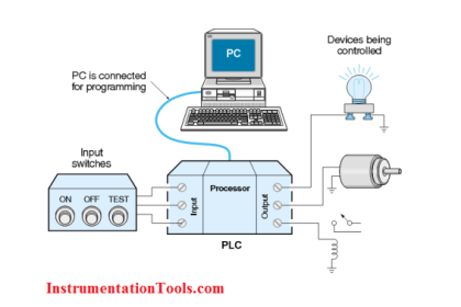
  4. What do the designations “L1” and “L2” refer to in ladder-logic electrical diagrams?
  5. Suppose switch TSL has a trip setting of 105 deg F (falling) and a deadband value of 2 deg F. Explain how this switch will respond to a rising and falling temperature.
  6. Suppose we wished to have switch TSHH activate two different alarm lights instead of just one. Modify the circuit diagram accordingly.
Share Your Comments for each Question.

If you liked this article, then please subscribe to our YouTube Channel for PLC and SCADA video tutorials.

You can also follow us on Facebook and Twitter to receive daily updates.

Don't Miss Our Updates
Be the first to get exclusive content straight to your email.
We promise not to spam you. You can unsubscribe at any time.
Invalid email address
You've successfully subscribed !

Continue Reading

How to Use an SQL Server with Indusoft Web Studio?
PLC Program for Flow Totalizer
PLC Programming Projects for Beginners
Simulate Different Values for Pressure Instrument Under Test
Why Are Charcoal and Salt Added to an Earthing Pit?
PLC Example to Control LEDs Via Switches
Share This Article
Facebook Whatsapp Whatsapp LinkedIn Copy Link
Share
3 Comments
  • Alikhan says:
    January 11, 2021 at 12:40 pm

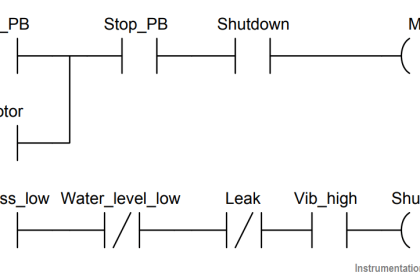
    1. TSH uses a normally open contact to prevent the turning on of the cooling water solenoid in the beginning of the process. Since the temperature is low at the starting point of the process. Hence, the temperature should increase firstly, then according to the particular temperature value TSH becomes enegized and its normally open contact is closed. Thus, the cooling water solenoid is on.

    2. TSL is de-energized when temperature is low. Therefore, it uses a normally closed contact to energize the low temperature indicator in the beginning of the process. Hence, the indicator exhibits the current temperature value at the starting moment, then the temperature is increasing, TSL is going to be energized. Threfore, its normally closed contact becomes an open contact. And now we don’t see low temperature indicator is as energinzed.

    3. The solenoid valve is energized merely at one particular moment, when TSH open contact is closed. Obviously, the solenoid valve allows to flow cooling water when energized.

    4. Phase 1 and Phase 2.

    5. TSL is not energized when temperature is low than 105-2 deg F. So, normally closed contact is still closed, but energized when temperature is more than 105+2. So, normally closed contact becomes open.

    6. To append new branch below for another alarm indicator as an output.

    It might be I have some mistakes in my explanation, be polite.
    And I will be appreciated If you correct my mistakes. Thank you!

    Reply
    • Mehar says:
      May 27, 2024 at 7:39 am

      Thank you

      Reply
  • arthur says:
    October 10, 2022 at 3:17 pm

    the question is why they use TSL and Tsh instead of N.C or N.O my answer is because it used as and temperature sensor and it will only activate once the predetermine temp set point is reach

    Reply

Leave a Reply Cancel reply

Your email address will not be published. Required fields are marked *

Stay Connected

128.3kFollowersLike
69.1kFollowersFollow
210kSubscribersSubscribe
38kFollowersFollow

Categories

Explore More

Raw Counts to Engineering Units : Conversion Formula
What is NOR Flash Memory in PLC?
Testing and Validation in PLC Development
What is 21 CFR in SCADA and HMI Systems?
Upload Option Disabled in Siemens PLC
Float-type Level Switch for Sensing Low Oil Level
Examples of PLC Programming using Boolean Functions
Allen Bradley SLC 500 PLC Programming

Keep Learning

PLC Programming Course Online Free

PLC Programming Course Online Free

Connecting Blocks in Functional Block Diagram

Connecting Blocks in Functional Block Diagram – Studio 5000

User Defined Function Blocks in PLC

What are User Defined Function Blocks in PLC?

PLC Handbook

PLC Handbook

PLC Demo Software

PLC Trainer Demo Download

Safety PLC Coding Practices

Safety PLC Coding Practices – Programming Recommendations

Emergency Stop Push button

Emergency Stop Switch Spurious Trip

Parameters of SRT_DINT instruction

Tia Portal – OB20 Time Delay Interrupt Organization Block

Learn More

PID Tuning recommendations

PID Tuning Recommendations based on Process Dynamics

Reduce Control Valve Noise

How to Reduce the Control Valve Noise?

Minimum Oil Circuit Breaker (MOCB) Spares & Service

Minimum Oil Circuit Breaker (MOCB) No Vendor Spares & Service

Cable Glands

Using of MCT instead of Cable Glands on the Cabinets

Split Range Control for Temperature Control Application

Split Range Control Working Principle

Retro-Reflective Sensor

What is a Retro-Reflective Sensor? – Principle, Applications

annunciator-alarm-simulator

Alarm Simulator for Annunciator Logic

hall-effect-sensor

Hall Effect Sensor Working Principle Animation

Menu

  • About
  • Privacy Policy
  • Copyright

Quick Links

  • Learn PLC
  • Helping Hand
  • Part Time Job

YouTube Subscribe

Follow US
All rights reserved. Reproduction in whole or in part without written permission is prohibited.
Welcome Back!

Sign in to your account

Username or Email Address
Password

Lost your password?