Inst ToolsInst ToolsInst Tools
  • Courses
  • Automation
    • PLC
    • Control System
    • Safety System
    • Communication
    • Fire & Gas System
  • Instrumentation
    • Design
    • Pressure
    • Temperature
    • Flow
    • Level
    • Vibration
    • Analyzer
    • Control Valve
    • Switch
    • Calibration
    • Erection & Commissioning
  • Interview
    • Instrumentation
    • Electrical
    • Electronics
    • Practical
  • Q&A
    • Instrumentation
    • Control System
    • Electrical
    • Electronics
    • Analog Electronics
    • Digital Electronics
    • Power Electronics
    • Microprocessor
Search
  • Books
  • Software
  • Projects
  • Process
  • Tools
  • Basics
  • Formula
  • Power Plant
  • Root Cause Analysis
  • Electrical Basics
  • Animation
  • Standards
  • 4-20 mA Course
  • Siemens PLC Course
Reading: DP Level Transmitter Auto Calibration
Share
Notification Show More
Font ResizerAa
Inst ToolsInst Tools
Font ResizerAa
  • Courses
  • Design
  • PLC
  • Interview
  • Control System
Search
  • Courses
  • Automation
    • PLC
    • Control System
    • Safety System
    • Communication
    • Fire & Gas System
  • Instrumentation
    • Design
    • Pressure
    • Temperature
    • Flow
    • Level
    • Vibration
    • Analyzer
    • Control Valve
    • Switch
    • Calibration
    • Erection & Commissioning
  • Interview
    • Instrumentation
    • Electrical
    • Electronics
    • Practical
  • Q&A
    • Instrumentation
    • Control System
    • Electrical
    • Electronics
    • Analog Electronics
    • Digital Electronics
    • Power Electronics
    • Microprocessor
Follow US
All rights reserved. Reproduction in whole or in part without written permission is prohibited.
Inst Tools > Blog > Level Measurement > DP Level Transmitter Auto Calibration

DP Level Transmitter Auto Calibration

Last updated: September 14, 2016 5:48 pm
Editorial Staff
Level Measurement
3 Comments
Share
7 Min Read
SHARE

 Introduction

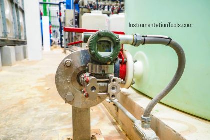
DPharp transmitters with advanced software functionality eliminate this time consuming task. With maintenance shops getting smaller, finding equipment that allows us to do more with less becomes a priority.Level transmitter configuration can be very time consuming. Calculations required to determine proper range values for traditional transmitters can become complex due to the physical layout of an application.
Level Transmitters Auto Calibration
DP Level Transmitter Auto Calibration

Application

Using typical smart or conventional products all of the following must be considered:

  1. The specific gravity of the process;
  2. Precise location of 0% and 100%;
  3. Specific gravity of the capillary fill fluid or sealing liquid (for impulse tubing);
  4. Vertical height of capillary or impulse piping;
  5. Exact orientation of the transmitter to the vessel;
  6. Vertical distance between the flanges.

Depending on the application, the vessel may be open (referencing atmosphere), or closed (under some blanket pressure).

Elevation is typically used when the vessel is closed. To reference blanket pressures, a low side wet leg or remote seal must be used. The low side pressure creates a negative force on the transmitter equal to the vertical height times the specific gravity of the fill fluid.

Suppression is positive pressure created on the high side of the transmitter typically due to a zero point above the transmitter. It is normally employed in an open vessel referencing atmosphere. This is a positive pressure equal to the vertical distance between the 0% point and the transmitter times the specific gravity of the liquid.

Elevation/suppression distance almost never agrees with the P&ID because actual piping (or remote seal capillaries) do not form exacting angles in the field. In most cases, the precise vertical height is not known until the unit is installed.

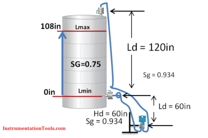
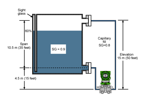
Span is the vertical distance of the process times the specific gravity: Figure 1. 10.5 * 0.9 = 9.45 mH2O (31.5 inH2O).
Calibration range is the calculated 0 and 100% taking into consideration positive and negative pressures. In figure 1, the following applies:

0% = H – L
(4.5 x 0.8) – (15 x 0.8)
3.6 – 12 = -8.4 mH2O (-28 inH2O)

100% = H – L
(4.5 x 0.8) + (10.5 x 0.9) – (15 x 0.8)
3.6 + 9.45 – 12 = 1.05 mH2O (3.5 inH2O)

The calibration range is:
-8.4 to 1.05 mH2O (-28 to 3.5 inH2O)

The information required to perform the calculation is not readily available. It exists in vendors instruction manuals, P&ID’s, but not until the unit is actually installed will all the variables be known because the process piping and capillaries do not form exacting angles in the field.

Solution

DPharp has a smart level setup feature that eliminates the need for elevation/suppression calculations, making set up quick and painless.
Calibration is accomplished by simply following these four steps:

  1. Span the transmitter to the process, height * specific gravity of 0 to 9.45 mH2O (0 to 31.5 inH2O) using the BT200 in C21: LRV andC22: HRV.
  2. Install to the prss using either capillaries or impulse tubing.
  3. Bring the process to a zero (4mA) condition.
  4. Through the BT200 execute H10: Auto LRV in the H: AUTO SET menu.

DPharp will calculate the total elevation/suppression and automatically setup the device for that installation. It will even correct the values in software at C21 LRV -28 and C22 HRV 3.5 so the customer can print and record the actual configuration for their maintenance documents.

But what if I cannot bring my process to zero? I have installed the unit, fluid is now in the tank, and the output of the transmitter does not agree with my sight glass. What do I do?

Most transmitters can only make adjustments at 0% or 100%. DPharp can make adjustments anywhere with full elevation or suppression. Once the transmitter is programmed with the correct span, all that is needed is a known point in the process (usually provided by the sight glass.) The output can be adjusted in one of two ways.

  1. Simply adjust the encoder on the DPharp until the output reaches the known point. In figure 1, the output would be adjusted to 60%.
  2. The correct value can be entered into J10: Zero Adj. In the case of this example, the proper output value of 60% would be entered. The amount of deviation can be viewed in J11: Zero Dev.

DPharp’s digital sensing technology makes this possible. With analog sensing technologies (like capacitance sensors), range changes often necessitate a re-calibration or a trimming of the A/D converter to achieve specified performance. The digital DPharp sensor has no A/D converter, no trimming is necessary. The new range is guaranteed to perform within specification.

Notes

  1. In level measurement, it is important to maintain a consistent reference pressure. On a closed tank system, this is most efficiently achieved by the use of remote seals and capillary systems.
  2. It is important to note that the span is to be calculated on process height x specific gravity of the process fluid, and will not necessarily agree with the physical height.
  3. Output will be linear to the level, regardless of fluid or blanketing system.
  4. Use of remote seals eliminates problems such as condensation in impulse piping, the requirement for maintenance of condensate pots and fill fluid leaking into the process.

Main Features of DPharp Transmitter

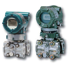
EJA110A Digital SolutionMain Features of DPharp

  • Best-in-class performance
  • ±0.03% Overpressure calibration protection
  • ±0.1% per 5 years long term stability
  • 100:1 turndown
  • ±0.065% accuracy

EJX110A Premium Value

  • ±0.1% per 10 years long term stability
  • 200:1 turndown
  • Best-in-class high accuracy, 0.04%
  • Multi-sensing output
  • Multi-variable transmitter as EJX family line-up
  • Safety as standard (IEC 61508)

Also Read: Calibration of DP Level Transmitter with Remote Seals
Don't Miss Our Updates
Be the first to get exclusive content straight to your email.
We promise not to spam you. You can unsubscribe at any time.
Invalid email address
You've successfully subscribed !

Continue Reading

Float Level Measurement
Differential Pressure Transmitters Compensated Leg Systems
Nuclear Interface Level Measurement Principle, Limitations, Installation and Calibration
How to Measure Density using DP Transmitter?
Ultrasonic Level Transmitter Principle, Limitations, Calibration and configuration
Non-Contacting Radar Level Transmitter Working Principle
Share This Article
Facebook Whatsapp Whatsapp LinkedIn Copy Link
Share
3 Comments
  • Pankaj dodiya says:
    December 4, 2015 at 4:17 am

    Thanks

    Reply
  • vijay says:
    March 18, 2016 at 2:46 pm

    thank you.

    Reply
  • Ako says:
    January 22, 2024 at 4:17 pm

    Very nice thank you. Do you have a course about pressure devices and instrumentation. And p&id.

    Reply

Leave a Reply Cancel reply

Your email address will not be published. Required fields are marked *

Stay Connected

128.3kFollowersLike
69.1kFollowersFollow
208kSubscribersSubscribe
38kFollowersFollow

Categories

Explore More

Basics of Differential Pressure Level Transmitters
Surface Detector Level Gauges (Plumb-bob)
Instruments Tapping Points – Common versus Individual
Hydrostatic Tank Gauging (HTG)
How Buoyant Force instruments Works ?
Open Tank DP Level Transmitter Calculations
What is a Level Switch? Types of Level Switches
Basics of Level Measurement

Keep Learning

Boiler Three Element Controller Philosophy

Boiler Three Element Controller Philosophy

Capillary Remote Seal Leave Measurement

Siemens Pressure Transmitter with Remote Seals Calculations
level-transmitter-calibration-procedure

Level Transmitter Calibration Procedure

Which instrument is at fault in this system

Which Instrument is at Fault in this System?

Level Transmitter

What is a Bridle?

Reflex Level Gauge Parts

What is Reflex Level Gauge?

interface-level-measurement-need

Level Measurement Terminology

Capacitance Level Switch Working Principle

Capacitance Level Switch Working Principle

Learn More

Supervisory Control

Supervisory Control

Free Siemens PLC Training Course

Free Siemens PLC Training Course

Ultrasonic Sensors Objective Questions

Ultrasonic Sensors Objective Questions

Pressure Gauge Design

How to Select a Pressure Gauge

electrical-drives-questions-answers

Electrical Drives Questions & Answers

Inverse Transducers Objective Questions

Inverse Transducers Objective Questions

FIFO and LIFO Sequences in PLC

What are FIFO and LIFO Sequences in PLC?

Control Valve Parts

Basic Parts of Control Valves

Follow US
All rights reserved. Reproduction in whole or in part without written permission is prohibited.
Welcome Back!

Sign in to your account

Username or Email Address
Password

Lost your password?