Inst ToolsInst ToolsInst Tools
  • Courses
  • Videos
  • Q & A
    • Interview
      • Instrumentation
      • Electronics
      • Electrical
      • Practical Questions
    • MCQ
      • Instrumentation MCQ
      • Electrical MCQ
      • Electronics MCQ
      • Control Systems MCQ
      • Analog Electronics MCQ
      • Digital Electronics MCQ
      • Power Electronics MCQ
      • Microprocessor MCQ
      • Multiple Choice Questions
  • EE
    • Electronics
      • Electronics Q & A
      • Electronic Basics
      • Electronic Devices & Circuits
      • Electronics Animation
      • Digital Electronics
    • Electrical
      • Electrical Basics
      • Electrical Q & A
      • Power Electronics
      • Electrical Machines
      • Electrical Animation
      • Power Systems
      • Switchgear & Protection
      • Transmission & Distribution
  • Measure
    • Control Valves
    • Calibration
    • Temperature
    • Pressure
    • Flow
    • Level
    • Analyzers
    • Switches
    • Vibration
    • Solenoid Valve
  • Control
    • PLC Tutorials
    • Control Systems
    • Safety Instrumented System (SIS)
    • Communication
    • Fire & Gas System
  • More
    • Design
    • Tools
    • Animation
    • Basics
    • Formulas
    • Standards
    • TextBooks
    • Common
    • Software
    • Excel Tools
    • Erection & Commissioning
    • Process Fundamentals
    • Videos
    • Books
Search
All rights reserved. Reproduction in whole or in part without written permission is prohibited.
Reading: Relay Loop Back Circuit
Share
Notification Show More
Font ResizerAa
Inst ToolsInst Tools
Font ResizerAa
  • Courses
  • PLC Tutorials
  • Control Systems
Search
  • Courses
  • Videos
  • Q & A
    • Interview
    • MCQ
  • EE
    • Electronics
    • Electrical
  • Measure
    • Control Valves
    • Calibration
    • Temperature
    • Pressure
    • Flow
    • Level
    • Analyzers
    • Switches
    • Vibration
    • Solenoid Valve
  • Control
    • PLC Tutorials
    • Control Systems
    • Safety Instrumented System (SIS)
    • Communication
    • Fire & Gas System
  • More
    • Design
    • Tools
    • Animation
    • Basics
    • Formulas
    • Standards
    • TextBooks
    • Common
    • Software
    • Excel Tools
    • Erection & Commissioning
    • Process Fundamentals
    • Videos
    • Books
Follow US
All rights reserved. Reproduction in whole or in part without written permission is prohibited.
Inst Tools > Blog > Instrumentation Design > Relay Loop Back Circuit

Relay Loop Back Circuit

Last updated: December 4, 2019 3:10 pm
Editorial Staff
Instrumentation Design
1 Comment
Share
5 Min Read
SHARE

Basic Relay Circuit :

Electromechanical_Relays Circuit

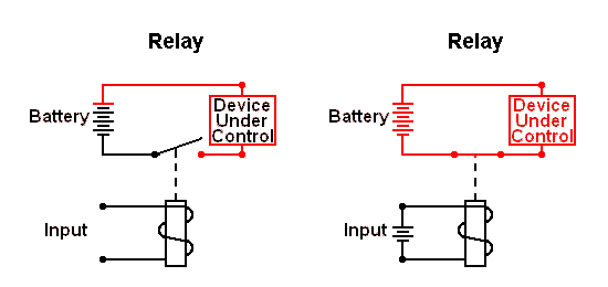
Relays are switches that open and close circuits electromechanically or electronically. Relays control one electrical circuit by opening and closing contacts in another circuit.

As relay diagrams show, when a relay contact is normally open (NO), there is an open contact when the relay is not energized. When a relay is energized then the normally open (NO) contact becomes normally closed (NC) thus the current path will be closed and power will be delivered to the load (device under control). when relay is de-energized then Normally closed contact becomes Normally open & power to the load will be turned off.

Relay holding/latch circuit :

The Holding Circuit (or Latch) has commonly been used to turn on a device with a momentary signal. A brief electrical pulse actuates a holding circuit which keeps power applied after the pulse has ended

The drawing below shows the basic holding/latch circuit. To simplify the diagram, both the relay coil and Device Under Control (load) use the same power source.

Latching Circuit

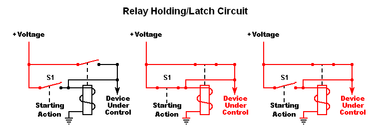
First Diagram: Electricity cannot flow to the load (Device Under Control) because of the normally open contacts of switch (S1) and the relay. Second Diagram: closing S1, energizing the relay coil and powering the load (device under control). Third Diagram: Opening off Switch S1, allowing its contacts to open. Normally this would break the circuit and the power will be turned off to the load; however, the closed relay contacts continue supplying current to both the relay coil and the load.

Now we will see how to turn off the load. Our next circuit addresses the problem.

Holding Circuit

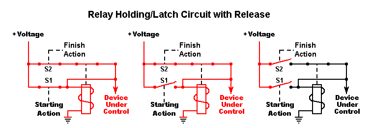
In this circuit we’ve added a normally closed switch (S2). Its purpose is to stop, means powering off the load.

First Diagram: closing S1 and powering the load. Second Diagram: S1 opens, but the latch circuit keeps the load on. Third diagram: When the closed switch S2 opens, de-energizing the relay and stopping the load. Since the relay contacts are now open, closing S2 will not power the load again.

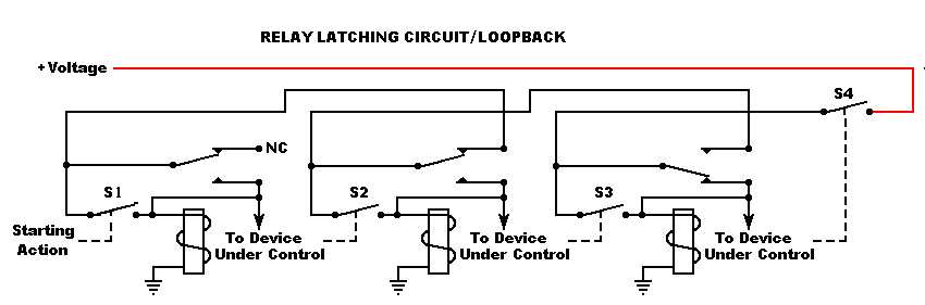
Relay Loop Back Circuit :

Design a relay circuit where each device can turn off the preceding device/load. we have 3 different loads & each have a relay circuit for controlling the power to the load separately one at a time. All loads & Relay have common power source. Each relay have independent input pulse signal to activate the relay & power the load. if load 1 energized then load 2 & load 3 will be in de-energized state. if load 2 energized then load 1 & load 3 will be in de-energized state. if load 3 energized then load 1 & load 2 will be in de-energized state.

The Loop-Back Circuit And finally, the last circuit! Sometimes it’s desirable to have several devices in series. The circuit below shows how each device can turn off the preceding device. This is sometimes called a “loop-back” circuit.

Relay Loop Back Circuit

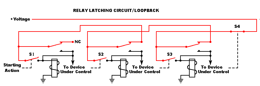
Switches S1, S2 and S3 and the normally open relay contacts prevent all the loads in off state.

Relay Holding Diagram

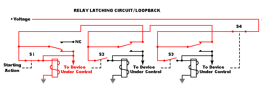
When switch S1 closes, energizing the 1st latch, Energizing the load 1.

Relay Latching Diagram

Load 1 will be in energized state, even though S1 has opened.

Relay Latching Diagram 2

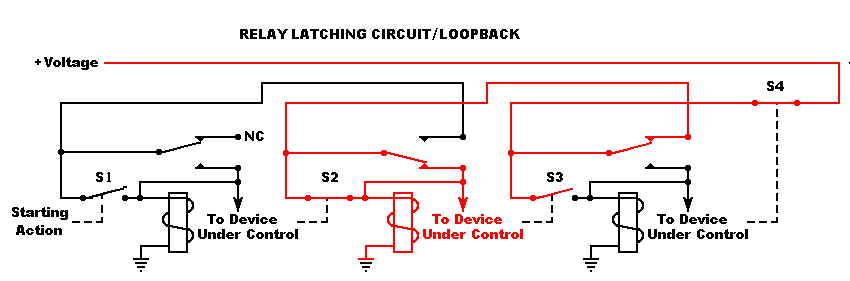
When closing S2, energizing the latch of relay-2, turning off the load 1 and energizing the load 2.

Relay Latching Diagram 3

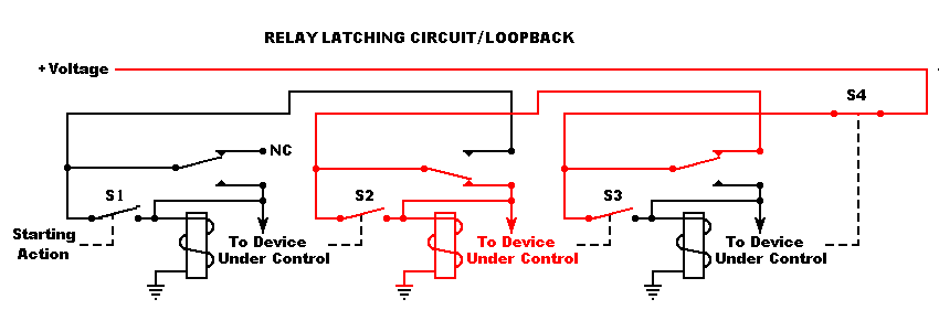
Load 2 will be in energized state, even though S2 has opened.

Relay Latching Diagram 4

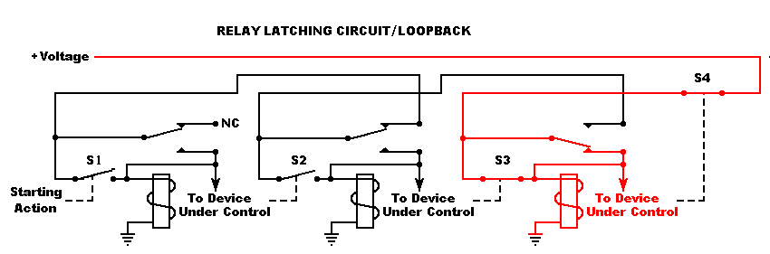
When closing S3, energizing the 3rd latch (relay 3), turning off the load 2 and energizing the load 3.

Relay Latching Diagram 5

Load 3 will be in energized state, even though S3 has opened.

When openings S4, releasing the latch and stopping the load 3. Since none of the relays are latched, none of the loads will be energized, even if S4 closes again.

Relay Latching Diagram 6

Source : scioly

Don't Miss Our Updates
Be the first to get exclusive content straight to your email.
We promise not to spam you. You can unsubscribe at any time.
Invalid email address
You've successfully subscribed !

Continue Reading

What is Nest Loading? – DCS and PLC Control Systems
Level Instruments Design Rules
Pneumatic Valves and Cylinders Sizing – Part 1
Magnetic Flow Meters Installation Guidelines
How-to Create Instrument Loop Diagram (ILD)?
What is SAMA Diagram?
Share This Article
Facebook Whatsapp Whatsapp LinkedIn Copy Link
Share
1 Comment
  • mohammed hussain says:
    May 19, 2017 at 8:12 am

    Really u doing great job god bless u

    Reply

Leave a Reply Cancel reply

Your email address will not be published. Required fields are marked *

Stay Connected

128.3kFollowersLike
69.1kFollowersFollow
208kSubscribersSubscribe
38kFollowersFollow

Categories

Explore More

Blast Furnace Panel Modification to Reduce Down Time by 60 to 70%
How to Select a Fuse ?
Types of Cables, Purpose, Advantages, Disadvantages, Applications
Redundant Power Supply for Critical Field Panels
What is Static Pressure Limit in DP Transmitter ?
How to Select an Actuator for Valve
Electrical and Instrumentation – Automation Pre-engineering Documents
Instrument Numbering Philosophy
What is Marshalling Cabinet?
Design Basis for Fire Detection and Alarm System

Keep Learning

Purpose of Instrument Loop Diagrams

Purpose of Loop Diagrams

Pneumatic Cylinder Air Flow Calculation

Pneumatic Cylinder Air Flow Calculation

Solenoid Operated Valves and Latching Valves

Solenoid Operated Valves and Latching Valves

Field Instrument package

Package System Architecture – Control & Instrumentation

Thermowell Problems

Thermowell Problems

Orifice Plate Sizing

Orifice Sizing Guidelines and Thumb Rules with Flowchart

Steam Tracing

Steam Tracing

Motor Primary Resistance Starter

Electrical Motor Starter Circuits

Discover More

belt conveyors principle

Conveyor : Belt, Screw, Pneumatic, Hydraulic, Roller, Chain, Bucket, Vibratory

Split Phase Motor

Single Phase AC Induction Motors

How to Update the Firmware Version of your PLC

How to Update the Firmware Version of your PLC? – TIA Portal

Hydrostatic level transmitter Formula

Hydrostatic Level Transmitter Questions

DeltaV System to Excel

How to Export Data from DeltaV System to Excel

Applications of Photo diodes

Applications of Photo diodes

Troubleshooting a Biased Transistor

Troubleshooting a Biased Transistor

Analog Electronics Objective Questions

Analog Electronics Objective Questions – Set 10

Follow US
All rights reserved. Reproduction in whole or in part without written permission is prohibited.
Welcome Back!

Sign in to your account

Username or Email Address
Password

Lost your password?