Inst ToolsInst ToolsInst Tools
  • Ask
  • Courses
  • Videos
  • Q & A
    • Interview
      • Instrumentation
      • Electronics
      • Electrical
      • Practical Questions
    • MCQ
      • Instrumentation MCQ
      • Electrical MCQ
      • Electronics MCQ
      • Control Systems MCQ
      • Analog Electronics MCQ
      • Digital Electronics MCQ
      • Power Electronics MCQ
      • Microprocessor MCQ
      • Multiple Choice Questions
  • EE
    • Electronics
      • Electronics Q & A
      • Electronic Basics
      • Electronic Devices & Circuits
      • Electronics Animation
      • Digital Electronics
    • Electrical
      • Electrical Basics
      • Electrical Q & A
      • Power Electronics
      • Electrical Machines
      • Electrical Animation
      • Power Systems
      • Switchgear & Protection
      • Transmission & Distribution
  • Measure
    • Control Valves
    • Calibration
    • Temperature
    • Pressure
    • Flow
    • Level
    • Analyzers
    • Switches
    • Vibration
    • Solenoid Valve
  • Control
    • PLC Tutorials
    • Control Systems
    • Safety Instrumented System (SIS)
    • Communication
    • Fire & Gas System
  • More
    • Design
    • Tools
    • Animation
    • Basics
    • Formulas
    • Standards
    • TextBooks
    • Common
    • Software
    • Excel Tools
    • Erection & Commissioning
    • Process Fundamentals
    • Videos
    • Books
Search
All rights reserved. Reproduction in whole or in part without written permission is prohibited.
Reading: Basics of Voltage Regulators
Share
Notification Show More
Font ResizerAa
Inst ToolsInst Tools
Font ResizerAa
  • Courses
  • PLC Tutorials
  • Control Systems
Search
  • Ask
  • Courses
  • Videos
  • Q & A
    • Interview
    • MCQ
  • EE
    • Electronics
    • Electrical
  • Measure
    • Control Valves
    • Calibration
    • Temperature
    • Pressure
    • Flow
    • Level
    • Analyzers
    • Switches
    • Vibration
    • Solenoid Valve
  • Control
    • PLC Tutorials
    • Control Systems
    • Safety Instrumented System (SIS)
    • Communication
    • Fire & Gas System
  • More
    • Design
    • Tools
    • Animation
    • Basics
    • Formulas
    • Standards
    • TextBooks
    • Common
    • Software
    • Excel Tools
    • Erection & Commissioning
    • Process Fundamentals
    • Videos
    • Books
Follow US
All rights reserved. Reproduction in whole or in part without written permission is prohibited.
Inst Tools > Blog > Electronic Devices & Circuits > Basics of Voltage Regulators

Basics of Voltage Regulators

Last updated: April 16, 2019 8:12 am
Editorial Staff
Electronic Devices & Circuits
No Comments
Share
3 Min Read
SHARE

While filters can reduce the ripple from power supplies to a low value, the most effective approach is a combination of a capacitor-input filter used with a voltage regulator.

A voltage regulator is connected to the output of a filtered rectifier and maintains a constant output voltage (or current) despite changes in the input, the load current, or the temperature.

The capacitor-input filter reduces the input ripple to the regulator to an acceptable level. The combination of a large capacitor and a voltage regulator helps produce an excellent power supply.

Most regulators are integrated circuits and have three terminals—an input terminal, an output terminal, and a reference (or adjust) terminal.

The input to the regulator is first filtered with a capacitor to reduce the ripple to The regulator reduces the ripple to a negligible amount.

In addition, most regulators have an internal voltage reference, shortcircuit protection, and thermal shutdown circuitry. They are available in a variety of voltages, including positive and negative outputs, and can be designed for variable outputs with a minimum of external components.

Typically, voltage regulators can furnish a constant output of one or more amps of current with high ripple rejection.

Three-terminal regulators designed for fixed output voltages require only external capacitors to complete the regulation portion of the power supply, as shown in Below Figure.

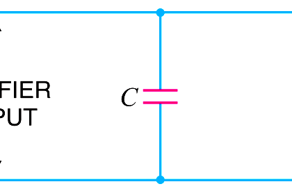
Filtering is accomplished by a large-value capacitor between the input voltage and ground.

An output capacitor (typically ) is connected from the output to ground to improve the transient response. 0.1 mFto1.0mF 610%.

Basics of Voltage Regulators

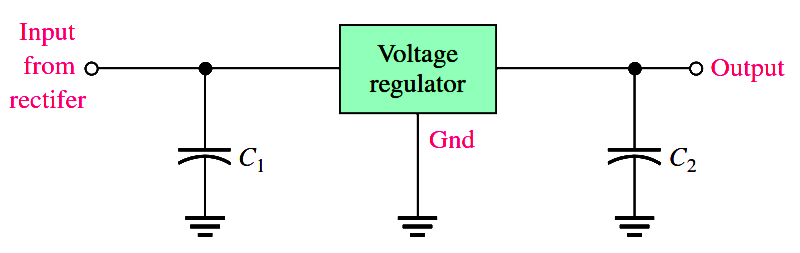
Fig : A voltage regulator with input and output capacitors.

A basic fixed power supply with a +5 V voltage regulator is shown in Below Figure. Specific integrated circuit three-terminal regulators with fixed output voltages are available in the market.

full-wave-bridge-rectifier-with-voltage-regulator

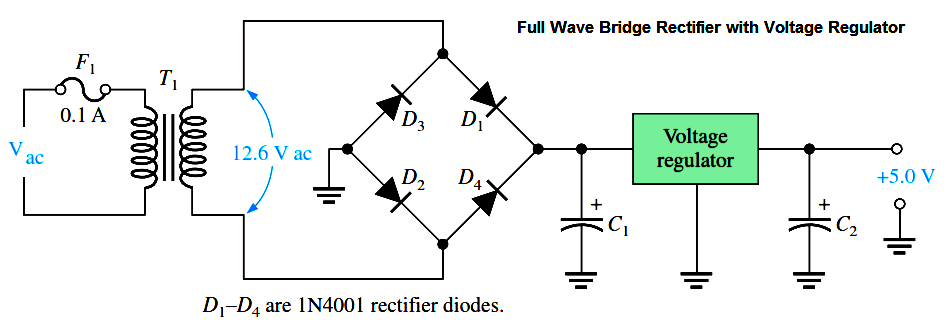
Fig : A basic +5.0 V regulated power supply.

Percent Regulation

The regulation expressed as a percentage is a figure of merit used to specify the performance of a voltage regulator. It can be in terms of input (line) regulation or load regulation.

Line Regulation

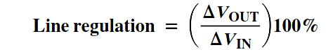
The line regulation specifies how much change occurs in the output voltage for a given change in the input voltage.

It is typically defined as a ratio of a change in output voltage for a corresponding change in the input voltage expressed as a percentage.

voltage-regulator-line-regulation

Load Regulation

The load regulation specifies how much change occurs in the output voltage over a certain range of load current values, usually from minimum current (no load, NL) to maximum current (full load, FL).

It is normally expressed as a percentage and can be calculated with the following formula:

voltage-regulator-load-regulation

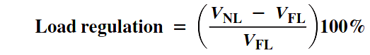
where VNL is the output voltage with no load and VFL is the output voltage with full (maximum) load.

Don't Miss Our Updates
Be the first to get exclusive content straight to your email.
We promise not to spam you. You can unsubscribe at any time.
Invalid email address
You've successfully subscribed !
Optoisolator Working Principle
Transistor as an Amplifier in Common Emitter
Diode Limiters/Clippers Operation
Time Base Generator
Working of NPN Transistor
Share This Article
Facebook Whatsapp Whatsapp LinkedIn Copy Link
Share
Leave a Comment

Leave a Reply Cancel reply

Your email address will not be published. Required fields are marked *

Stay Connected

128.3kFollowersLike
69.1kFollowersFollow
208kSubscribersSubscribe
38kFollowersFollow

Categories

Recent Comments

  • Kamli on Top Free PLC Software
  • Guifty Shimica on Top Non-PLC Certification Courses for Automation Professionals
  • Guifty Shimica on Top Non-PLC Certification Courses for Automation Professionals
  • MIHARITSOA Aina Sitraka on Top Non-PLC Certification Courses for Automation Professionals

Related Articles

Ideal Diode Characteristics Curve

Difference between ideal diode & conventional diode

light-emitting-diode-theory

Light Emitting Diode Operation

Methods of Transistor Biasing

Methods of Transistor Biasing

Current Limiting Resistor

Resistors Principle & Applications

Combining Independent Current Sources in Parallel

Combining Independent Current Sources in Parallel

Choke Input Filter Operation

Choke Input Filter Operation

transistor-base-bias

Transistor Base Bias

Voltage Divider Rule

Voltage Divider Rule

More Articles

Needle Valve Body Design

What is Needle Valve ?

SC connector

What is a Network Connector? – Types of Connectors

Control Valve Positioners

Control Valve Positioners

DCS Alarm and Setpoint

Setpoints and Alarms in Control System

Digital Electronics Multiple Choice Questions

Encoders Objective Questions

two-way communication between PLC systems

Transferring Data Across PLC Systems – TSEND_C and TRCV_C

Thermocouple Law of Intermediate Metals

Thermocouples Law of Intermediate Metals

PLC Logic Example on Multiple Switches and Motors

PLC Logic Example on Multiple Switches and Motors

Follow US
All rights reserved. Reproduction in whole or in part without written permission is prohibited.
Welcome Back!

Sign in to your account

Username or Email Address
Password

Lost your password?