Inst ToolsInst ToolsInst Tools
  • Courses
  • Automation
    • PLC
    • Control System
    • Safety System
    • Communication
    • Fire & Gas System
  • Instrumentation
    • Design
    • Pressure
    • Temperature
    • Flow
    • Level
    • Vibration
    • Analyzer
    • Control Valve
    • Switch
    • Calibration
    • Erection & Commissioning
  • Interview
    • Instrumentation
    • Electrical
    • Electronics
    • Practical
  • Q&A
    • Instrumentation
    • Control System
    • Electrical
    • Electronics
    • Analog Electronics
    • Digital Electronics
    • Power Electronics
    • Microprocessor
  • Request
Search
  • Books
  • Software
  • Projects
  • Process
  • Tools
  • Basics
  • Formula
  • Power Plant
  • Root Cause Analysis
  • Electrical Basics
  • Animation
  • Standards
  • 4-20 mA Course
  • Siemens PLC Course
Reading: Foundation Fieldbus Signal Conversion Formula
Share
Font ResizerAa
Inst ToolsInst Tools
Font ResizerAa
  • Courses
  • Design
  • PLC
  • Interview
  • Control System
Search
  • Courses
  • Automation
    • PLC
    • Control System
    • Safety System
    • Communication
    • Fire & Gas System
  • Instrumentation
    • Design
    • Pressure
    • Temperature
    • Flow
    • Level
    • Vibration
    • Analyzer
    • Control Valve
    • Switch
    • Calibration
    • Erection & Commissioning
  • Interview
    • Instrumentation
    • Electrical
    • Electronics
    • Practical
  • Q&A
    • Instrumentation
    • Control System
    • Electrical
    • Electronics
    • Analog Electronics
    • Digital Electronics
    • Power Electronics
    • Microprocessor
  • Request
Follow US
All rights reserved. Reproduction in whole or in part without written permission is prohibited.
Inst Tools > Blog > Communication > Foundation Fieldbus Signal Conversion Formula

Foundation Fieldbus Signal Conversion Formula

Last updated: January 6, 2019 8:53 am
Editorial Staff
Communication
No Comments
Share
2 Min Read
SHARE

Every foundation fieldbus transmitters have mainly two types of scales or ranges. one is XD scale & second one is OUT Scale.

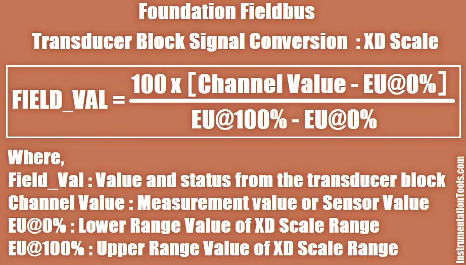
Transducer scaling (XD_SCALE) is applied to the value from the channel (sensor measurement) to produce the FIELD_VAL in percent.

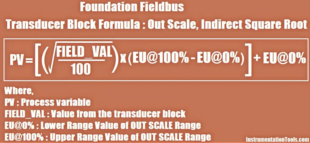
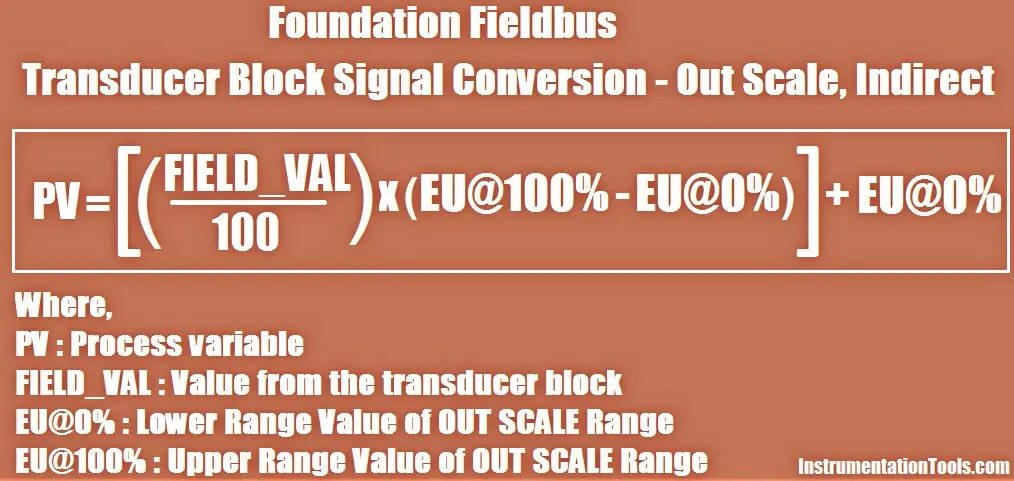
The OUT_SCALE is normally the same as the transducer, but if L_TYPE is set to Indirect or Ind Sqr Root, OUT_SCALE determines the conversion from FIELD_VAL to the output. OUT_SCALE provides scaling for PV.

The PV is always the value that the block will place in OUT if the mode is Auto.

You can set the signal conversion type with the Linearization Type (L_TYPE) parameter.  You can view the converted signal (in percent of XD_SCALE) through the FIELD_VAL parameter.

Foundation Fieldbus Signal Conversion Formula

You can choose from direct, indirect, or indirect square root signal conversion with the L_TYPE parameter

Direct

Direct signal conversion allows the signal to pass through the accessed channel input value (or the simulated value when simulation is enabled)

PV = Channel Value

Indirect

Indirect signal conversion converts the signal linearly to the accessed channel input value (or the simulated value when simulation is enabled) from its specified range (XD_SCALE) to the range and units of the PV and OUT parameters (OUT_SCALE).

Foundation Fieldbus Indirect Formula

Indirect Square Root

Indirect Square Root signal conversion takes the square root of the value computed with the indirect signal conversion and scales it to the range and units of the PV and OUT parameters.

Foundation Fieldbus Indirect Square Root Formula

Don't Miss Our Updates
Be the first to get exclusive content straight to your email.
We promise not to spam you. You can unsubscribe at any time.
Invalid email address
You've successfully subscribed !

Continue Reading

FF Function Blocks
Foundation Fieldbus (FF) Segment Topology
What is a Fieldbus?
OTDR Testing
WirelessHART Network Protocol
What is HART, Foundation Fieldbus & Profibus ?
Share This Article
Facebook Whatsapp Whatsapp LinkedIn Copy Link
Share
Leave a Comment

Leave a Reply Cancel reply

Your email address will not be published. Required fields are marked *

Stay Connected

128.3kFollowersLike
69.1kFollowersFollow
210kSubscribersSubscribe
38kFollowersFollow

Categories

Explore More

MODBUS ASCII Communication Protocol Explained
Fieldbus Coupling Devices
Foundation Fieldbus Installation and Best Practices
Basics for CAN Bus Protocol – Controller Area Network
What is HART Protocol ?
Foundation Fieldbus Interview Questions and Answers
Wireless HART Communication Protocol Overview
Industrial Automation Communication Protocols

Keep Learning

Fieldbus Transmitter Calibration

Fieldbus Transmitters Calibration and Ranging

Distributed Control System Architecture for Foundation Fieldbus Field Instruments

What is Foundation Fieldbus (FF) ?

7 OSI Layers of Communications

7 OSI Layers of Communication

Foundation Fieldbus Tutorials

Foundation Fieldbus Tutorials

WirelessHART field instruments

WirelessHART device Configuration

IPSec

What is IPSec? – Internet Protocol Security

HART Communication

HART Communication Protocol Overview

WirelessHART Device Terminals

WirelessHART Network Gateway Device

Learn More

Analyzer Sample Conditioning

Sodium Analyzer Problems and Troubleshooting Steps

Types-of-diodes

Different Types of Diodes

cable-trays-glossary

Cable Trays Glossary

induction motor torque versus speed

Induction Motor Torque Versus Slip

Active Barrier

What is a Active Barrier ?

Troubleshooting PLC Current Loops

Troubleshooting Current Loops with Voltage Measurement

PLC Program using Timers

PLC Timers Program

Weigh feeders Principle

What is a Weigh Feeder?

Menu

  • About
  • Privacy Policy
  • Copyright

Quick Links

  • Learn PLC
  • Helping Hand
  • Part Time Job

YouTube Subscribe

Follow US
All rights reserved. Reproduction in whole or in part without written permission is prohibited.
Welcome Back!

Sign in to your account

Username or Email Address
Password

Lost your password?