Inst ToolsInst ToolsInst Tools
  • Courses
  • Automation
    • PLC
    • Control System
    • Safety System
    • Communication
    • Fire & Gas System
  • Instrumentation
    • Design
    • Pressure
    • Temperature
    • Flow
    • Level
    • Vibration
    • Analyzer
    • Control Valve
    • Switch
    • Calibration
    • Erection & Commissioning
  • Interview
    • Instrumentation
    • Electrical
    • Electronics
    • Practical
  • Q&A
    • Instrumentation
    • Control System
    • Electrical
    • Electronics
    • Analog Electronics
    • Digital Electronics
    • Power Electronics
    • Microprocessor
  • Request
Search
  • Books
  • Software
  • Projects
  • Process
  • Tools
  • Basics
  • Formula
  • Power Plant
  • Root Cause Analysis
  • Electrical Basics
  • Animation
  • Standards
  • 4-20 mA Course
  • Siemens PLC Course
Reading: Open Tank Interface Level Measurement
Share
Notification Show More
Font ResizerAa
Inst ToolsInst Tools
Font ResizerAa
  • Courses
  • Design
  • PLC
  • Interview
  • Control System
Search
  • Courses
  • Automation
    • PLC
    • Control System
    • Safety System
    • Communication
    • Fire & Gas System
  • Instrumentation
    • Design
    • Pressure
    • Temperature
    • Flow
    • Level
    • Vibration
    • Analyzer
    • Control Valve
    • Switch
    • Calibration
    • Erection & Commissioning
  • Interview
    • Instrumentation
    • Electrical
    • Electronics
    • Practical
  • Q&A
    • Instrumentation
    • Control System
    • Electrical
    • Electronics
    • Analog Electronics
    • Digital Electronics
    • Power Electronics
    • Microprocessor
  • Request
Follow US
All rights reserved. Reproduction in whole or in part without written permission is prohibited.
Inst Tools > Blog > Level Measurement > Open Tank Interface Level Measurement

Open Tank Interface Level Measurement

Last updated: August 30, 2019 11:41 am
Editorial Staff
Level Measurement
No Comments
Share
4 Min Read
SHARE

Open Tank Interface Level Measurement 

Interface level can be measured in a vessel or tank using differential pressure transmitter or pressure transmitter.

An interface level measurement is only possible if the densities of the two products in the tank/vessel remains same.

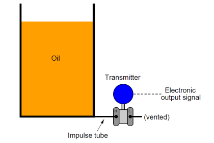
if we are using DP Transmitter then the HP side is connected to the tank tapping point and LP side is vent to atmosphere or we can use a pressure transmitter also.

The DP Transmitter calibration parameters will vary depending on installation & seal system also. Generally we can see three possibilities of installation of a transmitter in the field.

They are :

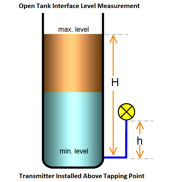
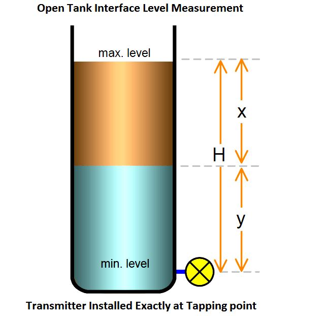
  1. Transmitter installed Exactly at tapping point ( Ideal & preferred way of installation)
  2. Transmitter installed above tapping point ( Not preferable, Chance of bubble formation in the impulse line)
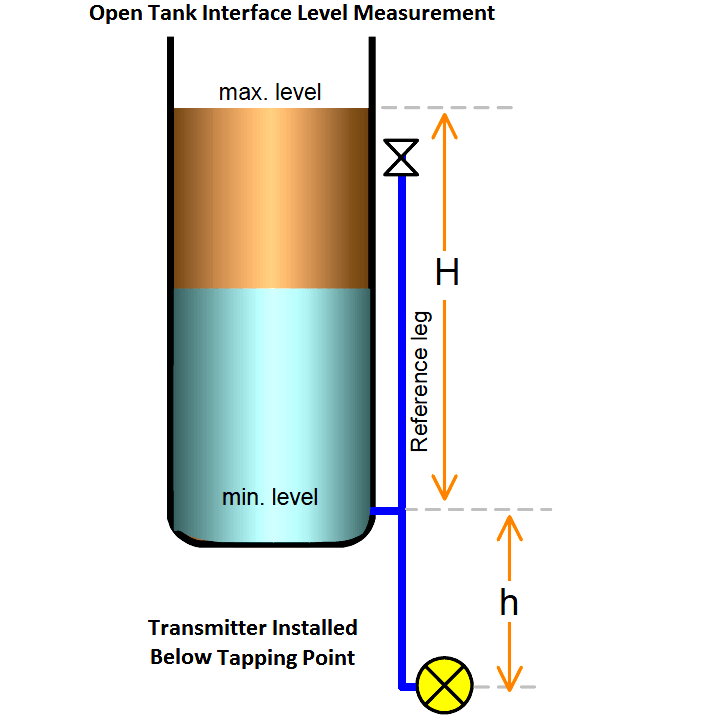
  3. Transmitter installed below tapping point (Error can be compensated effectively)

So we have to calibrate the transmitter depending on the type of installation in the field. The calibration formula will vary slightly depending on the installation.Every transmitter have two important parameters, they are Lower Range Value (LRV) & Upper Range Value (URV). We have to calculate the LRV & URV values based on type of installation. The below figures with formulas dictates the calculations. After calculating the values, configure the same parameters in the transmitter using HART communicator.

Here we are discussing two types of seal systems : with seal & without seal,

  • With Seal System : The impulse line is filled with special fluid like with glycerine, glycol etc
  • Without Seal System : Tank / Vessel fluid will be filled with the impulse lines

Normal installation (transmitter mounted leveled with the tapping point)

Open Tank Interface Level measurement principle

With seal system;

LRV = ρu • g • H , or,
LRV = (SGu • H)

URV = ρl • g • H , or,
URV = (SGl • H)

Without seal system;

(assume the leg is always filled with lower liquid)

LRV = ρu • g • H , or,
LRV= (SGu • H)

URV = ρl • g • H
URV = (SGl • H)

Elevated-Zero installation (transmitter mounted above the tapping point)

Open Tank Interface Level measurement Above Tapping Point

With seal system;

Zero Elevation = − (ρf • g • h)

Min. Head = ρu • g • H , or, = (SGu • h)

Span = ρl • g • H , or, = (SGl • h)

Without seal system; 

Not preferable

Therefore, for calibration;

4mA (LRV) = Min. Head + Zero Elevation

20mA (URV) = Span + Zero Elevation

Suppressed-Zero installation (transmitter mounted below the tapping point)

Open Tank Interface Level measurement Below Tapping Point

With seal system;

Zero Suppression = ρf • g • h

Min. Head = ρu • g • H , or, = (SGu • h)

Span = ρl • g • H , or, = (SGl • h)

Without seal system;

Zero Suppression = ρl • g • h

Min. Head = ρu • g • H , or, = (SGu • h)

Max. Head or Span = ρl • g • H

Therefore, for calibration;

4mA (LRV) = Min. Head + Zero Suppression

20mA (URV) = Span + Zero Suppression

NOTE:

ρp = density of process liquid in the tank
ρf = density of fill-liquid in the tubing
ρu = density of upper liquid
ρl = density of lower liquid
SGp = std. gravity of process liquid.
SGf = std. gravity of fill liquid
SGu = std. gravity of upper liquid
SGl = std. gravity of lower liquid

Article Source : N. Asyiddin
Don't Miss Our Updates
Be the first to get exclusive content straight to your email.
We promise not to spam you. You can unsubscribe at any time.
Invalid email address
You've successfully subscribed !

Continue Reading

Level Gauges Objective Questions and Answers – Instrumentation
Level Instruments General Specifications
Open and Closed Tank Level Calculations
Types of Level Gauges
Differential Pressure (DP) Level transmitter Installed Above Tapping Point
Air Purge or Air Bubbler Level Measurement
Share This Article
Facebook Whatsapp Whatsapp LinkedIn Copy Link
Share
Leave a Comment

Leave a Reply Cancel reply

Your email address will not be published. Required fields are marked *

Stay Connected

128.3kFollowersLike
69.1kFollowersFollow
210kSubscribersSubscribe
38kFollowersFollow

Categories

Explore More

How to Find LRV and URV of Closed Tank DP Level Transmitter
Closed Tank Remote Seal Capillary type DP Transmitter
Servo Level Transmitter Principle
Remote Seal Transmitters Ranging Calculation
Level Gauge Design
How Tilt Level Switch Works ?
Basics of Differential Pressure Level Transmitters
Advantages & Disadvantages of Level Measurement Systems

Keep Learning

Magnatic Level Indicators Working Animation

Magnetic Level Indicators Working Animation

How to Install Ultrasonic Level Transmitters 5

How to Install Ultrasonic Level Transmitters

Servo Tank Gauge Level Principle

Servo Tank Gauges Working Principle

RF Level Sensors Principle

RF Level Switches Working Principle

interface-level-measurement-need

Level Measurement Terminology

Density Measurement using Remote Seal Transmitters

Remote Seal Differential Pressure Transmitters Principle

Instruments Tapping Points

Instruments Tapping Points – Common versus Individual

The 5 ways Ultrasonic Sensors Work

The 5 ways Ultrasonic Sensors Work

Learn More

PLC Pressure Switch Ladder Diagram

Relays in Ladder Logic Tutorials

Smart DP transmitter Formula

DP Transmitter Error Calculations

What is Transformer Bushing

What is Transformer Bushing? Working Principle

cascade temperature controller

How to Analyze a Cascade Control Loop?

How to Use Symbol Factory Software for Graphic Design in HMI or SCADA

How to Use Symbol Factory Software for Graphic Design in HMI or SCADA?

EcoStruxure Machine Expert - HVAC - Programming Software

How to Write a Program in Ecostruxure Machine Expert HVAC Software?

Displacer Type Density Transmitter

Displacer Type Density Transmitter Question

Manchester encoding

Foundation Fieldbus Electrical Parameters

Menu

  • About
  • Privacy Policy
  • Copyright

Quick Links

  • Learn PLC
  • Helping Hand
  • Part Time Job

YouTube Subscribe

Follow US
All rights reserved. Reproduction in whole or in part without written permission is prohibited.
Welcome Back!

Sign in to your account

Username or Email Address
Password

Lost your password?