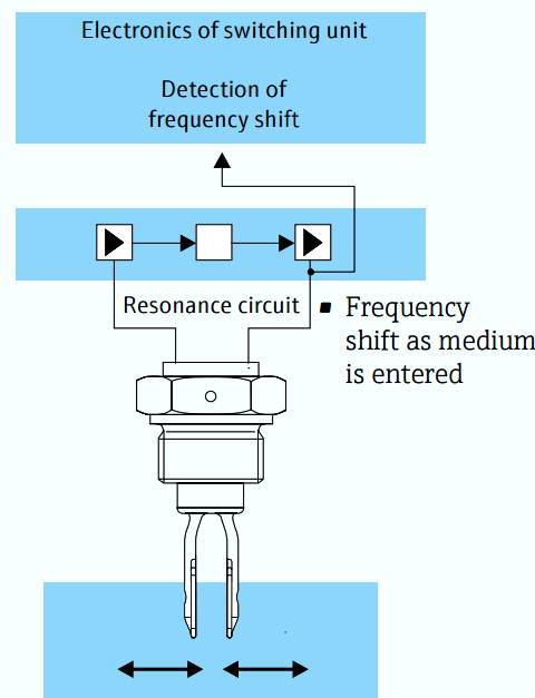
Point level detection in liquids
A tuning fork sensor oscillates at its resonant frequency. The drive works piezoelectrically. The oscillating frequency changes as the fork enters the medium. The change is analyzed and translated into a switching signal.
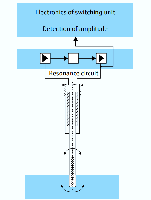
Point level detection in bulk solids
A single-rod or fork oscillating system is used as sensor in the Soliphant family. The oscillating system (single rod/fork) is excited to its resonant frequency. The oscillation amplitude is damped as the product covers the sensor. Maintenance and calibration or specific settings are not required. External vibration or flow properties of the medium do not impair measurement.
Capacitance Point level detection in liquids and bulk solids
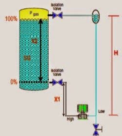
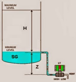
Capacitance level measurement covers a wide range of applications which are not limited to process engineering. Simple and cost-effective probes offer many possibilities for point level detection in liquids and bulk solids. This measuring principle is particularly suited to applications involving aggressive media and heavy build-up
The capacitance level measurement principle is based on the capacity change of a capacitor due to a change in level. The probe (rod or rope) and the silo wall form the two electrodes of a capacitor. As product enters the electric field between the probe and the silo wall, the capacity increases. This capacity change is analyzed and leads, with the appropriate setting, to switching.
The sensors are largely unaffected by low build-up formation as long as the product does not create a bridge between the probe and the silo wall. Probes with active build-up compensation are used for media prone to strong build-up.
Source : E + H