Inst ToolsInst ToolsInst Tools
  • Courses
  • Automation
    • PLC
    • Control System
    • Safety System
    • Communication
    • Fire & Gas System
  • Instrumentation
    • Design
    • Pressure
    • Temperature
    • Flow
    • Level
    • Vibration
    • Analyzer
    • Control Valve
    • Switch
    • Calibration
    • Erection & Commissioning
  • Interview
    • Instrumentation
    • Electrical
    • Electronics
    • Practical
  • Q&A
    • Instrumentation
    • Control System
    • Electrical
    • Electronics
    • Analog Electronics
    • Digital Electronics
    • Power Electronics
    • Microprocessor
  • Request
Search
  • Books
  • Software
  • Projects
  • Process
  • Tools
  • Basics
  • Formula
  • Power Plant
  • Root Cause Analysis
  • Electrical Basics
  • Animation
  • Standards
  • 4-20 mA Course
  • Siemens PLC Course
Reading: Basics of Ohm’s Law
Share
Font ResizerAa
Inst ToolsInst Tools
Font ResizerAa
  • Courses
  • Design
  • PLC
  • Interview
  • Control System
Search
  • Courses
  • Automation
    • PLC
    • Control System
    • Safety System
    • Communication
    • Fire & Gas System
  • Instrumentation
    • Design
    • Pressure
    • Temperature
    • Flow
    • Level
    • Vibration
    • Analyzer
    • Control Valve
    • Switch
    • Calibration
    • Erection & Commissioning
  • Interview
    • Instrumentation
    • Electrical
    • Electronics
    • Practical
  • Q&A
    • Instrumentation
    • Control System
    • Electrical
    • Electronics
    • Analog Electronics
    • Digital Electronics
    • Power Electronics
    • Microprocessor
  • Request
Follow US
All rights reserved. Reproduction in whole or in part without written permission is prohibited.
Inst Tools > Blog > Electronic Devices & Circuits > Basics of Ohm’s Law

Basics of Ohm’s Law

Last updated: December 31, 2017 5:34 am
Editorial Staff
Electronic Devices & Circuits
1 Comment
Share
2 Min Read
SHARE

In 1827 the German physicist George Ohm published a pamphlet entitled “The Galvanic Circuit Investigated Mathematically”. It contained one of the first efforts to measure currents and voltages and to describe and relate them mathematically. One result was a statement of the fundamental relationship we now call Ohm’s Law.

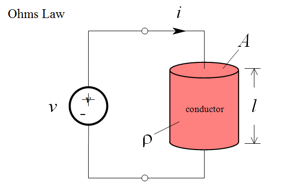
Consider a uniform cylinder of conducting material, to which a voltage has been connected. The voltage will cause charge to flow, i.e. a current:

Derivation-of-Ohms-Law

Ohm found that in many conducting materials, such as metal, the current is always proportional to the voltage. Since voltage and current are directly proportional, there exists a proportionality constant R, called resistance, such that:

Ohms-Law

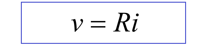
This is Ohm’s Law. The unit of resistance (volts per ampere) is referred to as the ohm, and is denoted by the capital Greek letter omega, Ω.

We refer to a construction in which Ohm’s Law is obeyed as a resistor.

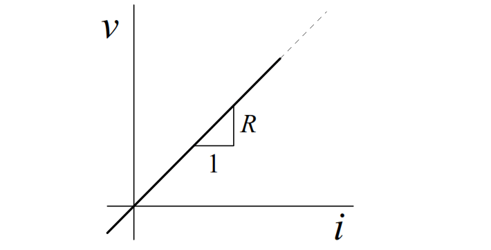
The ideal resistor relationship is a straight line through the origin:

Ohms-Law-Resistor-Linearity

Even though resistance is defined as R = v/i , it should be noted that R is a purely geometric property, and depends only on the conductor shape and the material used in the construction. For example, it can be shown for a uniform resistor that the resistance is given by:

Resistance-Equation

where l is the length of the resistor, and A is the cross-sectional area. The resistivity,  r ,  is  a  constant  of  the conducting  material  used  to  make  the resistor.

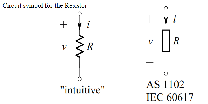
The circuit symbol for the resistor is shown below, together with the direction of current and polarity of voltage that make Ohm’s Law algebraically correct:

circuit-symbol-for-the-resistor

Example

Consider the circuit shown below.

Ohms-Law-Example

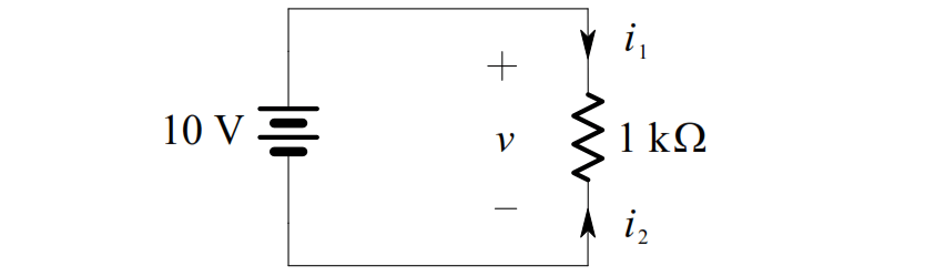
The voltage across the 1 kΩ resistor is, by definition of an ideal voltage source,

v(t ) = 10 V . Thus, by Ohm’s Law, we get:

i1  =  v/R = 10/1000 = 0.01 A = 10 mA

i2  =  –v/R = -10/1000 = -0.01 A = -10 mA

Note that i2  = –i1 , as expected

Don't Miss Our Updates
Be the first to get exclusive content straight to your email.
We promise not to spam you. You can unsubscribe at any time.
Invalid email address
You've successfully subscribed !

Continue Reading

Capacitor Filter Operation
Comparison of Transistor Configurations
Forward Bias & Reverse Bias Diode Working Animation
Transistors Questions & Answers
Transistor Collector Feedback Bias
Capacitor Filter Working Principle
Share This Article
Facebook Whatsapp Whatsapp LinkedIn Copy Link
Share
1 Comment
  • Azum Blaise Gabriel says:
    November 10, 2021 at 5:25 pm

    Very interesting and helpful.
    Young and upcoming engineers should take note

    Reply

Leave a Reply Cancel reply

Your email address will not be published. Required fields are marked *

Stay Connected

128.3kFollowersLike
69.1kFollowersFollow
210kSubscribersSubscribe
38kFollowersFollow

Categories

Explore More

Bipolar Junction Transistor Construction
Half Wave Voltage Doubler using Diodes
Half Wave Rectifier Principle
Ripple Voltage in Rectifiers
pi filter Operation
How a PN Junction Formed in a Diode
Light Emitting Diode Operation
Resistors Principle & Applications

Keep Learning

Schottky Diode Vs PN junction Diode

Difference between Schottky Diode and PN junction Diode

Transistor Amplifier Working Principle

Short Notes on Rectifiers & Filters

Short Notes on Rectifiers & Filters

full-wave-bridge-rectifier-with-voltage-regulator

Basics of Voltage Regulators

Diode-testing-with-multimeter

How to Test a Diode using Multimeter

Zener Diode Limiter Working

Zener Diode Limiter

Classification of Bridge Circuits

Classification of Bridge Circuits

Capacitively Coupled Multistage Transistor Amplifier

Capacitively Coupled Multistage Transistor Amplifier

Learn More

Positive Feedback Principle

What is Feedback ?

Ceramic Bearings

Everything You Need to Know About Ceramic Bearings

Nano Instrumentation Objective Questions

Nano Instrumentation Objective Questions

Basic Configuration of Motor Operated Valve

Rotork Motor Operated Valve Basic Configuration

Power Electronics Objective Questions

Current Source Inverters Objective Questions

Free Download SCADA Softwares

Free SCADA Software Download

Thermocouple Temperature Range

Thermocouple Properties, Temperature Ranges, Element Construction

Absolute and Gauge Pressure

Difference Between Absolute and Gauge Pressure

Menu

  • About
  • Privacy Policy
  • Copyright

Quick Links

  • Learn PLC
  • Helping Hand
  • Part Time Job

YouTube Subscribe

Follow US
All rights reserved. Reproduction in whole or in part without written permission is prohibited.
Welcome Back!

Sign in to your account

Username or Email Address
Password

Lost your password?