Inst ToolsInst ToolsInst Tools
  • Courses
  • Automation
    • PLC
    • Control System
    • Safety System
    • Communication
    • Fire & Gas System
  • Instrumentation
    • Design
    • Pressure
    • Temperature
    • Flow
    • Level
    • Vibration
    • Analyzer
    • Control Valve
    • Switch
    • Calibration
    • Erection & Commissioning
  • Interview
    • Instrumentation
    • Electrical
    • Electronics
    • Practical
  • Q&A
    • Instrumentation
    • Control System
    • Electrical
    • Electronics
    • Analog Electronics
    • Digital Electronics
    • Power Electronics
    • Microprocessor
  • Request
Search
  • Books
  • Software
  • Projects
  • Process
  • Tools
  • Basics
  • Formula
  • Power Plant
  • Root Cause Analysis
  • Electrical Basics
  • Animation
  • Standards
  • 4-20 mA Course
  • Siemens PLC Course
Reading: Differential Pressure Transmitter Calibration Procedure
Share
Font ResizerAa
Inst ToolsInst Tools
Font ResizerAa
  • Courses
  • Design
  • PLC
  • Interview
  • Control System
Search
  • Courses
  • Automation
    • PLC
    • Control System
    • Safety System
    • Communication
    • Fire & Gas System
  • Instrumentation
    • Design
    • Pressure
    • Temperature
    • Flow
    • Level
    • Vibration
    • Analyzer
    • Control Valve
    • Switch
    • Calibration
    • Erection & Commissioning
  • Interview
    • Instrumentation
    • Electrical
    • Electronics
    • Practical
  • Q&A
    • Instrumentation
    • Control System
    • Electrical
    • Electronics
    • Analog Electronics
    • Digital Electronics
    • Power Electronics
    • Microprocessor
  • Request
Follow US
All rights reserved. Reproduction in whole or in part without written permission is prohibited.
Inst Tools > Blog > Calibration > Differential Pressure Transmitter Calibration Procedure

Differential Pressure Transmitter Calibration Procedure

Last updated: June 24, 2018 8:55 pm
Editorial Staff
Calibration Pressure Measurement
9 Comments
Share
2 Min Read
SHARE

Differential Pressure Transmitter Calibration Procedure
differential-pressure-transmitter-calibration-procedure

Calibration Procedure :

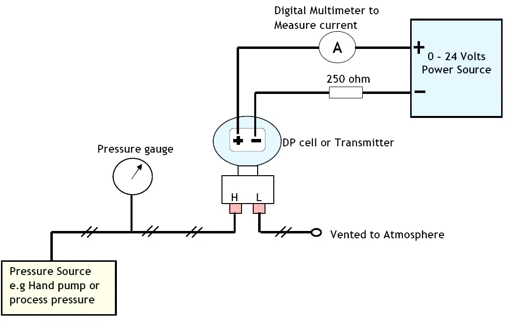
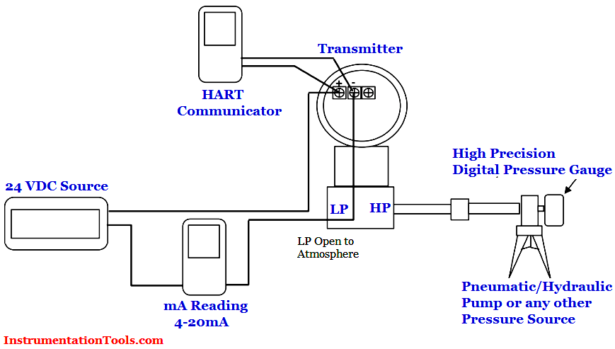
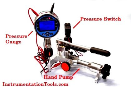
  1. Set up the differential pressure transmitter, HART communicator, power supply, hand pump, and the multimeter as below (see below calibration setup Diagram).
  2. Make sure the equalizing valve manifold is closed.
  3. Apply a pressure to the transmitter equal to a lower range pressure (usually it correspond to 4 mA in the transmitter output). For example we have 0 to 100 mBar calibrated range, then the lower range pressure is 0, or let’s say we have -2 psig to 5 psig then we have lower range pressure equal to -2 psig.
  4. Read the pressure in the transmitter LCD (or in the HART communicator). Adjust (if any) through the HART communicator so that the output of the transmitter (on LCD) is the same with the applied pressure.
  5. Read the mA output of the transmitter by using a multimeter. Adjust (if any) through the HART communicator so that the output of the transmitter (on multimeter) is 4 mA.
  6. Apply a pressure to the transmitter equal to an upper range pressure (usually it correspond to 20 mA in the transmitter output).
  7. Read the pressure in the transmitter LCD (or in the HART communicator). Adjust (if any) through the HART communicator so that the output of the transmitter (on LCD) is the same with the applied pressure.
  8. Read the mA output of the transmitter by using a multimeter. Adjust (if any) through the HART communicator so that the output of the transmitter (on multimeter) is 20 mA.

Differential Pressure Transmitter Calibration Setup

Typical tools required:
  1. 24 VDC power supply
  2. Multimeter digital
  3. Pneumatic hand pump (up to 600 psig)
  4. Hydraulic hand pump (up to 10.000 psig)
  5. Low pressure hand pump
  6. High precision digital test gauge
  7. HART communicator
  8. Screwdriver toolkit
 Note: point number 1, 2, 7, and 6 of the typical tools above can be replaced by a single multi-function calibrator available in the market.
Don't Miss Our Updates
Be the first to get exclusive content straight to your email.
We promise not to spam you. You can unsubscribe at any time.
Invalid email address
You've successfully subscribed !

Continue Reading

Differential Pressure Sensor for Filtration Monitoring
Solenoid Valve Functional Testing
Unbonded Strain Gauge Principle
Diaphragm Seal Material Selection
Control Valve Stroke Test Procedure
Uncertainty Calculations of Pressure Calibration
Share This Article
Facebook Whatsapp Whatsapp LinkedIn Copy Link
Share
9 Comments
  • Prashant says:
    October 5, 2016 at 4:33 am

    Why you have used 250 ohms resister there is it necessary to use when we have connected transmitter to PLC module.

    Reply
    • jayesh sundar gopinath says:
      July 9, 2017 at 4:58 pm

      we do not need 250 ohms resistance when we use plc module,however in the diagram it is clear they are using only a power source so for transmitter communication we need a resistor.

      Reply
    • Pappu Singh says:
      October 21, 2023 at 4:04 pm

      Because HART not used from without 250 oms

      Reply
  • Shanmugam says:
    November 19, 2016 at 6:23 am

    Thanks! good information, fantastic…..

    Reply
  • Md Mehebub says:
    January 25, 2017 at 11:50 am

    Thanks for your contribution.

    Reply
  • Onye says:
    August 7, 2018 at 12:59 pm

    Thanks for the knowledge sharing

    Reply
  • Rodge says:
    September 14, 2022 at 4:26 pm

    Why do we open the low side to atmosphere

    Reply
  • Md Farhan says:
    September 21, 2022 at 9:37 pm

    How to do DPT Flow transmitter Field Calibration?

    Reply
  • MD SHAHBAZ ALI says:
    May 3, 2025 at 7:04 am

    Because plc or Dcs card has present 250ohms resistance

    Reply

Leave a Reply Cancel reply

Your email address will not be published. Required fields are marked *

Stay Connected

128.3kFollowersLike
69.1kFollowersFollow
210kSubscribersSubscribe
38kFollowersFollow

Categories

Explore More

RTD Testing Methods in Calibration Laboratory
Level Transmitter Calibration Procedure
Basics of Differential Pressure Transmitters
Pressure Transmitter Calibration Procedure
Comparison of Pressure Instruments – Industrial Instrumentation
Pressure Gauge Problems
Multimeter – What Do Digits and Counts Mean?
Functions of Pressure Detectors

Keep Learning

Control Valve Calibration

How-to do Control Valve Calibration?

C-Type Bourdon Tube

Types of Bourdon Tube

Pressure Gauge Parts

Pressure Gauges with Bourdon Tube Principle

Current to Pressure Converter Calibration Procedure

Current to Pressure (I/P) Converter Calibration Procedure

Flow Meter Calibration Procedure

Flow Meter Calibration

U tube Manometer Working

Basics of Pressure

Calibration Instruments

Basics of Calibration

Gauge Display Scale

How to Read Gauge Analog Scales

Learn More

Address Resolution Protocol (ARP)

What is the Address Resolution Protocol? – Types of ARP

Vendor Selection in Procurement Service Cycle (For Industrial Projects)

Compliance Table Application (for Procurement Service Cycle)

Intelligent MCC

What is Smart or Intelligent MCC?

Dual-junction thermocouple circuit

Find Thermocouple Ouput Voltage

Accuracy, resolution, range, counts, digits and precision

Definition of Accuracy, Precision, Resolution, Range

Gas flow rate Formulas

Gas Flow Formulas

MTech Project Ideas for Electronics and Electrical Engineering

100 MTech Project Ideas for Electronics and Electrical Engineering

Loop Diagram

15 Loop Diagram Questions

Menu

  • About
  • Privacy Policy
  • Copyright

Quick Links

  • Learn PLC
  • Helping Hand
  • Part Time Job

YouTube Subscribe

Follow US
All rights reserved. Reproduction in whole or in part without written permission is prohibited.
Welcome Back!

Sign in to your account

Username or Email Address
Password

Lost your password?