Inst ToolsInst ToolsInst Tools
  • Ask
  • Courses
  • Videos
  • Q & A
    • Interview
      • Instrumentation
      • Electronics
      • Electrical
      • Practical Questions
    • MCQ
      • Instrumentation MCQ
      • Electrical MCQ
      • Electronics MCQ
      • Control Systems MCQ
      • Analog Electronics MCQ
      • Digital Electronics MCQ
      • Power Electronics MCQ
      • Microprocessor MCQ
      • Multiple Choice Questions
  • EE
    • Electronics
      • Electronics Q & A
      • Electronic Basics
      • Electronic Devices & Circuits
      • Electronics Animation
      • Digital Electronics
    • Electrical
      • Electrical Basics
      • Electrical Q & A
      • Power Electronics
      • Electrical Machines
      • Electrical Animation
      • Power Systems
      • Switchgear & Protection
      • Transmission & Distribution
  • Measure
    • Control Valves
    • Calibration
    • Temperature
    • Pressure
    • Flow
    • Level
    • Analyzers
    • Switches
    • Vibration
    • Solenoid Valve
  • Control
    • PLC Tutorials
    • Control Systems
    • Safety Instrumented System (SIS)
    • Communication
    • Fire & Gas System
  • More
    • Design
    • Tools
    • Animation
    • Basics
    • Formulas
    • Standards
    • TextBooks
    • Common
    • Software
    • Excel Tools
    • Erection & Commissioning
    • Process Fundamentals
    • Videos
    • Books
Search
All rights reserved. Reproduction in whole or in part without written permission is prohibited.
Reading: Transistor Collector Feedback Bias
Share
Notification Show More
Font ResizerAa
Inst ToolsInst Tools
Font ResizerAa
  • Courses
  • PLC Tutorials
  • Control Systems
Search
  • Ask
  • Courses
  • Videos
  • Q & A
    • Interview
    • MCQ
  • EE
    • Electronics
    • Electrical
  • Measure
    • Control Valves
    • Calibration
    • Temperature
    • Pressure
    • Flow
    • Level
    • Analyzers
    • Switches
    • Vibration
    • Solenoid Valve
  • Control
    • PLC Tutorials
    • Control Systems
    • Safety Instrumented System (SIS)
    • Communication
    • Fire & Gas System
  • More
    • Design
    • Tools
    • Animation
    • Basics
    • Formulas
    • Standards
    • TextBooks
    • Common
    • Software
    • Excel Tools
    • Erection & Commissioning
    • Process Fundamentals
    • Videos
    • Books
Follow US
All rights reserved. Reproduction in whole or in part without written permission is prohibited.
Inst Tools > Blog > Electronic Devices & Circuits > Transistor Collector Feedback Bias

Transistor Collector Feedback Bias

Last updated: September 27, 2016 5:44 am
Editorial Staff
Electronic Devices & Circuits
No Comments
Share
2 Min Read
SHARE

Transistor Collector Feedback Bias

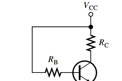
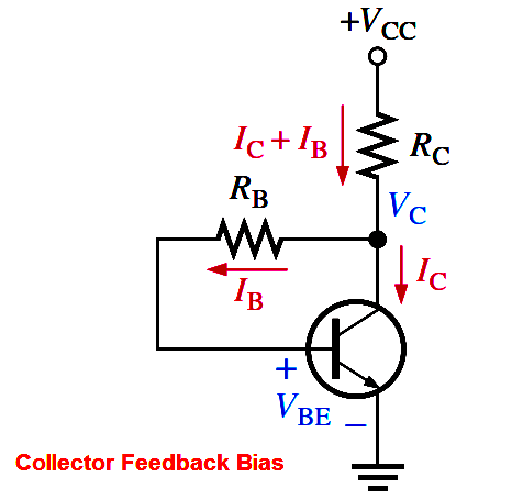
In Figure, the base resistor RB is connected to the collector rather than to VCC, as it was in the base bias arrangement discussed earlier. The collector voltage provides the bias for the base-emitter junction. The negative feedback creates an “offsetting” effect that tends to keep the Q-point stable. If IC tries to increase, it drops more voltage across RC, thereby causing VC to decrease. When VC decreases, there is a decrease in voltage across RB, which decreases IB. The decrease in IB produces less IC which, in turn, drops less voltage across RC and thus offsets the decrease in VC.

Analysis of a Collector-Feedback Bias Circuit 

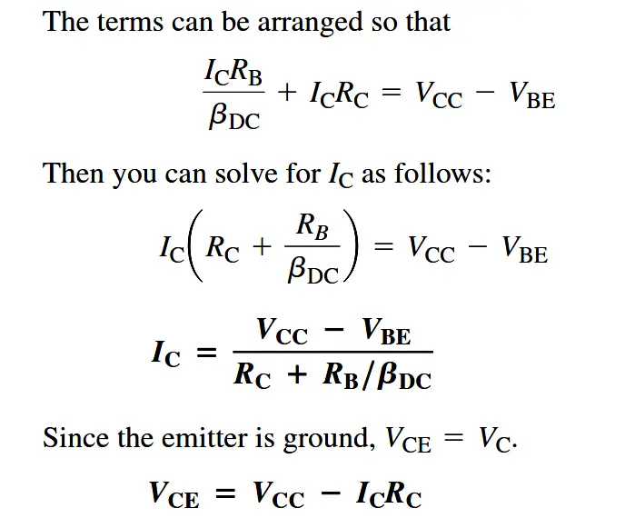
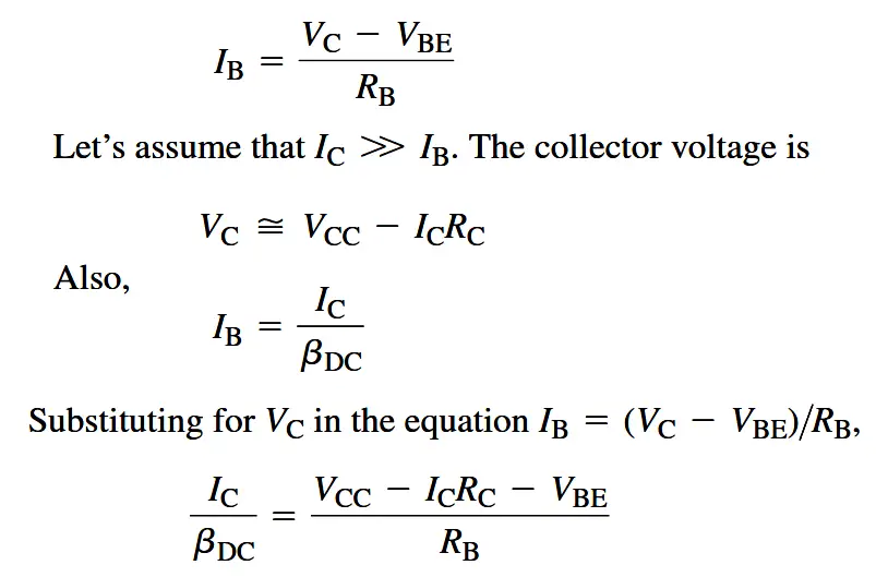
By Ohm’s law, the base current can be expressed as

Transistor-collector-feedback-bias-derivation.png

transistor_collector-feedback-bias-derivation


Q-Point Stability Over Temperature

Above Equation  shows that the collector current is dependent to some extent on βDC and VBE. This dependency, of course, can be minimized by making RC >> RB/βDC and VCC >> VBE. An important feature of collector-feedback bias is that it essentially eliminates the βDC and VBE dependency even if the stated conditions are met.

As you have learned, βDC varies directly with temperature, and VBE varies inversely with temperature. As the temperature goes up in a collector-feedback circuit, βDC goes up and VBE goes down. The increase in βDC acts to increase IC. The decrease in VBE acts to increase IB which, in turn also acts to increase IC. As IC tries to increase, the voltage drop across RC also tries to increase. This tends to reduce the collector voltage and therefore the voltage across RB, thus reducing IB and offsetting the attempted increase in IC and the attempted decrease in VC. The result is that the collector-feedback circuit maintains a relatively stable Q-point. The reverse action occurs when the temperature decreases.
Don't Miss Our Updates
Be the first to get exclusive content straight to your email.
We promise not to spam you. You can unsubscribe at any time.
Invalid email address
You've successfully subscribed !
How the Matrix Keypad works with a Micro controller?
Band Gap for Semiconductor Materials
Basics of Transistors
Full Wave Bridge Rectifier Peak Inverse Voltage
Energy Diagrams of PN Junction & Depletion Region
Share This Article
Facebook Whatsapp Whatsapp LinkedIn Copy Link
Share
Leave a Comment

Leave a Reply Cancel reply

Your email address will not be published. Required fields are marked *

Stay Connected

128.3kFollowersLike
69.1kFollowersFollow
208kSubscribersSubscribe
38kFollowersFollow

Categories

Recent Comments

  • Kamli on Top Free PLC Software
  • Guifty Shimica on Top Non-PLC Certification Courses for Automation Professionals
  • Guifty Shimica on Top Non-PLC Certification Courses for Automation Professionals
  • MIHARITSOA Aina Sitraka on Top Non-PLC Certification Courses for Automation Professionals

Related Articles

Transistor Collector Characteristic Curves

Transistor Collector Characteristic Curves

phototransistor symbols

Phototransistor Working Principle

Semiconductors Diodes Questions & Answers

Semiconductors Diodes Questions & Answers

Diode-vi-characteristic-curve-for-forward-bias

VI Characteristic of a Diode

Combining Independent Current Sources in Parallel

Combining Independent Current Sources in Parallel

Types-of-diodes

Different Types of Diodes

Zener Diode

Zener Diode Breakdown Characteristics

phototransistor-circuit

Phototransistor Circuit Example

More Articles

Mixing Process with Valve Control

PLC Mixing Process with Adjustable Timer and Valve Control

Control Valve Passing Problem after Overhauling Job

Control Valve Passing Problem after Overhauling Job

Calculate the Thermocouple’s Measurement Junction Temperature

Calculate the Thermocouple’s Measurement Junction Temperature

Electrical Power Distribution

Electrical Power Distribution

Electromagnetism Objective Questions and Answers

200+ Electromagnetism Objective Questions and Answers

Electrical Machines Questions and Answers

Rotating Magnetic Field Quiz

potentiometric level measurement principle

Potentiometric Level Measurement Principle

What is Gear Box Backlash

What is Gear Box Backlash ?

Follow US
All rights reserved. Reproduction in whole or in part without written permission is prohibited.
Welcome Back!

Sign in to your account

Username or Email Address
Password

Lost your password?