Inst ToolsInst ToolsInst Tools
  • Courses
  • Automation
    • PLC
    • Control System
    • Safety System
    • Communication
    • Fire & Gas System
  • Instrumentation
    • Design
    • Pressure
    • Temperature
    • Flow
    • Level
    • Vibration
    • Analyzer
    • Control Valve
    • Switch
    • Calibration
    • Erection & Commissioning
  • Interview
    • Instrumentation
    • Electrical
    • Electronics
    • Practical
  • Q&A
    • Instrumentation
    • Control System
    • Electrical
    • Electronics
    • Analog Electronics
    • Digital Electronics
    • Power Electronics
    • Microprocessor
  • Request
Search
  • Books
  • Software
  • Projects
  • Process
  • Tools
  • Basics
  • Formula
  • Power Plant
  • Root Cause Analysis
  • Electrical Basics
  • Animation
  • Standards
  • 4-20 mA Course
  • Siemens PLC Course
Reading: 5 Port 2 Position Valve Working Principle
Share
Font ResizerAa
Inst ToolsInst Tools
Font ResizerAa
  • Courses
  • Design
  • PLC
  • Interview
  • Control System
Search
  • Courses
  • Automation
    • PLC
    • Control System
    • Safety System
    • Communication
    • Fire & Gas System
  • Instrumentation
    • Design
    • Pressure
    • Temperature
    • Flow
    • Level
    • Vibration
    • Analyzer
    • Control Valve
    • Switch
    • Calibration
    • Erection & Commissioning
  • Interview
    • Instrumentation
    • Electrical
    • Electronics
    • Practical
  • Q&A
    • Instrumentation
    • Control System
    • Electrical
    • Electronics
    • Analog Electronics
    • Digital Electronics
    • Power Electronics
    • Microprocessor
  • Request
Follow US
All rights reserved. Reproduction in whole or in part without written permission is prohibited.
Inst Tools > Blog > Control Valves > 5 Port 2 Position Valve Working Principle

5 Port 2 Position Valve Working Principle

Last updated: April 18, 2019 11:03 pm
Editorial Staff
Control Valves Solenoid Valve
No Comments
Share
3 Min Read
SHARE

This instrument is not new to me. Since We started our pneumatics class on my third year in college, I already had the pleasure to meet this instrument. We even had to use this almost everyday, during our laboratory exercises. Its always present in all our pneumatic and hydraulic trainers. How does this stuff really work?

5 Port 2 Position Valve

5 Port 2 Position Valve

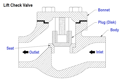
A valve is a device that regulates the flow of fluid (gases, liquids,fluidized solids, or slurries) by opening and closing or partially obstructing passage ways.

A 5/2 way directional valve from the name itself has 5 ports equally spaced and 2 flow positions. It can be use to isolate and simultaneously bypass a passage way for the fluid which for example should retract or extend a double acting cylinder.

There are variety of ways to have this valve actuated. A solenoid valve is commonly used, a lever can be manually twist or pinch to actuate the valve, an internal or external hydraulic or pneumatic pilot to move the shaft inside, sometimes with a spring return on the other end so it will go back to its original position when pressure is gone, or a combination of any of the mention above.

5 Port 2 Position Valve Animation

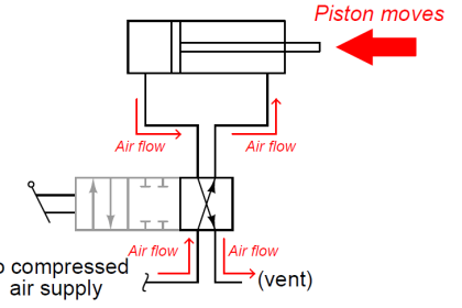
In the Illustration given, a single solenoid is used and a spring return is installed in the other end. The inlet pressure is connected to (P)1. (A)2 could possibly be connected to one end of the double acting cylinder where the piston will retract while (B)4 is connected to the other end that will make the piston extend.

The normal position when the solenoid is de-energized is that the piston rod is blocking (B)4 and pressure coming from (P)1 passes through (A)2 that will make the cylinder normally retracted.

When the solenoid is energized, the rod blocks (A)2 and pressure from (P)1 passes through (B)4 and will extend the cylinder and when the solenoid is de-energized, the rod bounces back to its original position because of the spring return. (E)3 and (E)5 is condemned or used as exhaust.

See how cool the combination of Electronics and Pneumatics is? There will be a lot more illustrations on pneumatics and hydraulics instruments coming soon that you shouldn’t missed.

I hope you enjoy reading.

Articles You May Like :

Directional Control Valves

2-way Solenoid Valve

Solenoid Valve’s Energize

SIS Final Control Elements

Electricity Magnetism

Don't Miss Our Updates
Be the first to get exclusive content straight to your email.
We promise not to spam you. You can unsubscribe at any time.
Invalid email address
You've successfully subscribed !

Continue Reading

What is a Float Control Valve? Types, Advantages, Disadvantages
What is ON/OFF Valve ?
JT Valve Working Principle
What is Gate Valve ?
Control Valve End Connection
Basics of Butterfly Valves
Share This Article
Facebook Whatsapp Whatsapp LinkedIn Copy Link
Share
Leave a Comment

Leave a Reply Cancel reply

Your email address will not be published. Required fields are marked *

Stay Connected

128.3kFollowersLike
69.1kFollowersFollow
210kSubscribersSubscribe
38kFollowersFollow

Categories

Explore More

Butterfly Valves Construction, Types, Stem & Bonnet Assembly
What is Valve Packing ?
Automated Block Valve (ABV)
Solenoid Valves Practical Problems
Exclusive Control Valve Sequence
What is Plug Valve ?
Digital Control Valve Working Principle
Difference between BDV and PSV

Keep Learning

3-way solenoid valves control instrument air pressure

Solenoid Valve’s Energized or De-energized State ?

Direct Lift Diaphragm Normally Open Solenoid Valve

Direct Lift Diaphragm Solenoid Valve Principle

Air Lock Relay Working Principle

Control Valve Air Lock Relay Working Principle

Gas Valve Sizing

Gas Valve Sizing

Pneumatic Actuators Types Animation

Types of Pneumatic Actuators Animation

Valve Software

Free Control Valve Software Download

Emerson ASCO Solenoid valve references

SIS Solenoid Valves – Safety PLC

What is Poppet Valve?

What is Poppet Valve? When we Use a Poppet Valve?

Learn More

Self-balancing Pneumatic Instrument Principles - 3

Self-balancing Pneumatic Instrument Principles

Introduction to Schneider PLC

Different Types of Schneider PLC

Capacitance Pressure Sensor Principle

Electronic Pressure Sensors Principle

What is Star Topology

Network Topologies Selection Factors and Comparison

Displacement Level Transmitter in situ calibration

Displacer (buoyancy) Level Transmitter Principle, Limitations, Design, Installation & Calibration

Zone vs Class - Division

Zone vs Class / Division

Deluge System for Transformer Protection

Deluge System for Transformer Protection Animation

Free Electronics Software Download

Menu

  • About
  • Privacy Policy
  • Copyright

Quick Links

  • Learn PLC
  • Helping Hand
  • Part Time Job

YouTube Subscribe

Follow US
All rights reserved. Reproduction in whole or in part without written permission is prohibited.
Welcome Back!

Sign in to your account

Username or Email Address
Password

Lost your password?