This post describes a flow measurement system utilizing a single orifice plate and three differential pressure transmitters. This configuration enhances redundancy and accuracy in flow measurement applications.
Objective: To provide a reliable and accurate flow measurement system using multiple differential pressure transmitters connected to a single orifice plate.
1 Orifice Plate with 3 Flow Transmitters
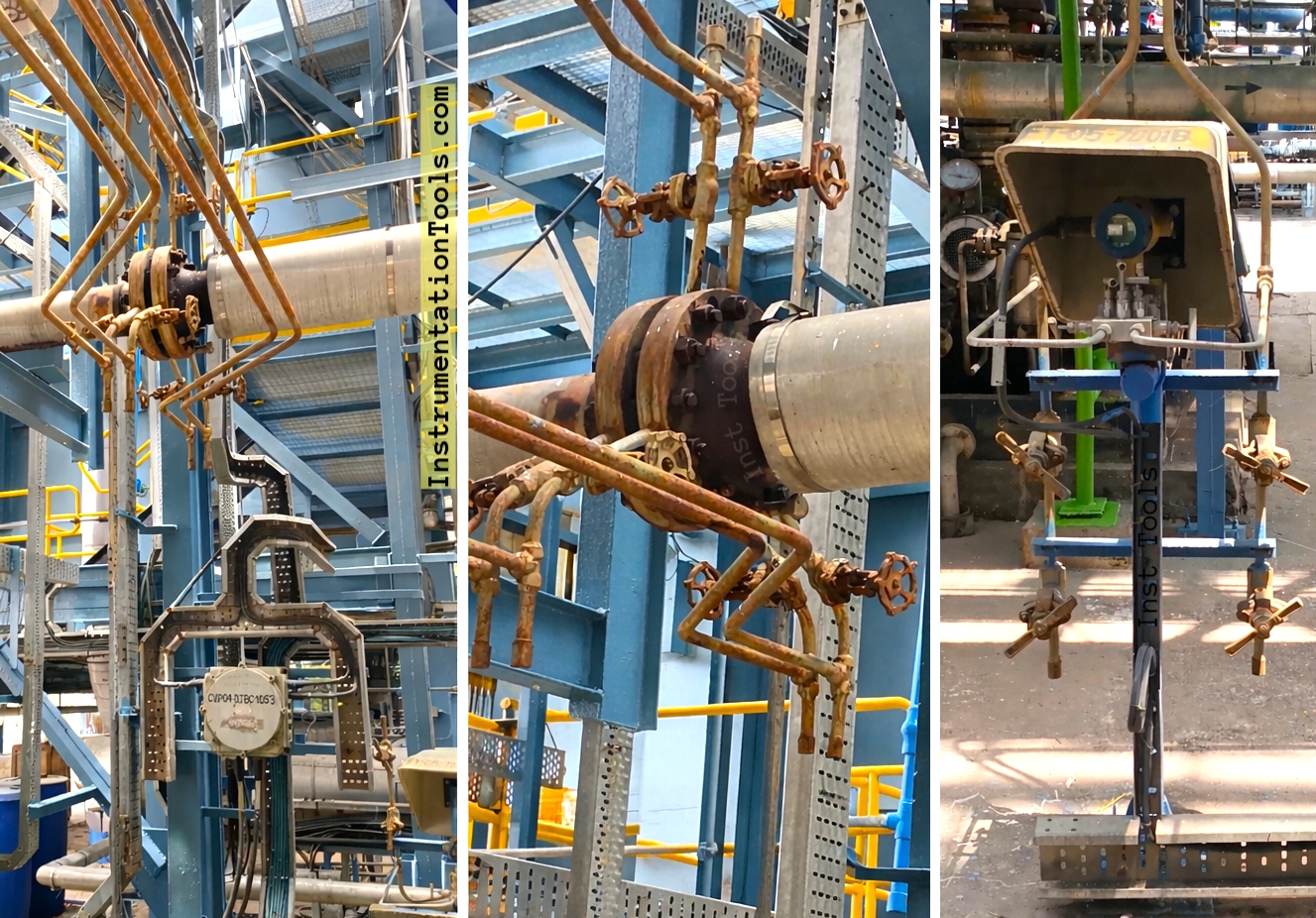
The system comprises the following key components:
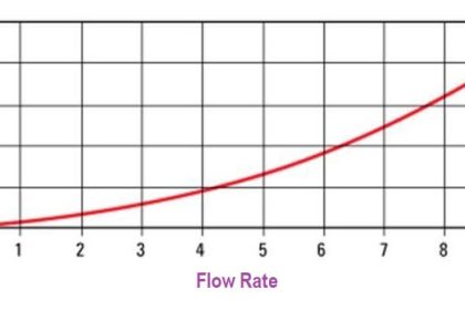
- Orifice Plate: A precisely manufactured plate with a calibrated bore, inserted into the pipeline to create a pressure drop proportional to the square of the flow rate.
- Differential Pressure Transmitters (DPT): Three independent DPTs, each calibrated to measure the differential pressure across the orifice plate.
- Tapping Points: Pressure taps located upstream and downstream of the orifice plate, providing pressure signals to the DPTs.
- Impulse Lines: Tubing connecting the tapping points to the DPTs. These lines must be properly sized and maintained to ensure accurate pressure transmission.
Configuration and Function
Each DPT is connected to the orifice plate via separate impulse lines and tapping points. This redundancy offers several advantages:
- Increased Reliability: If one DPT fails, the other two can continue to provide flow measurement data.
- Improved Accuracy: Averaging the readings from the three DPTs can reduce the impact of individual transmitter errors or noise.
- Enhanced Diagnostics: Discrepancies between the DPT readings can indicate potential problems with the orifice plate, impulse lines, or transmitters.
Video
The typical setup involves the following steps:
- Orifice Plate Installation: The orifice plate is installed in the pipeline, ensuring proper centering and alignment.
- Tapping Point Connections: Upstream and downstream tapping points are connected to each of the three DPTs via impulse lines. Careful attention is given to ensuring that all impulse lines are of equal length and properly sloped to prevent air or liquid accumulation.
- Transmitter: Each DPT is calibrated to measure the differential pressure across the orifice plate over the desired flow range.
- Signal Processing: The output signals from the three DPTs are typically fed into a signal processing system (e.g., a PLC or DCS) that performs averaging, error checking, and flow calculation.
- Flow Calculation: Using the differential pressure readings and the known characteristics of the orifice plate, the flow rate is calculated using standard flow equations.
| Component | Function |
|---|---|
| Orifice Plate | Creates a pressure drop proportional to flow rate. |
| Differential Pressure Transmitters | Measures differential pressure across the orifice plate. |
| Tapping Points | Provides pressure signals to the DPTs. |
| Impulse Lines | Connects tapping points to DPTs; transmits pressure. |
Advantages of Redundant Transmitter Configuration
- Increased uptime: The system continues to operate even if one transmitter fails.
- Improved data integrity: Averaging reduces the impact of individual sensor inaccuracies.
- Facilitates diagnostics: Comparing transmitter readings can reveal issues with the system.
- Enhances safety: More reliable flow measurement is crucial for maintaining process safety and control.
Maintenance Considerations
Regular maintenance is essential for ensuring the accuracy and reliability of the flow measurement system. Key maintenance tasks include:
- Impulse Line Inspection: Inspect impulse lines for leaks, blockages, and proper slope.
- Transmitter Calibration: Regularly calibrate the DPTs to ensure accurate readings. Recalibration should occur after any maintenance.
- Orifice Plate Inspection: Periodically inspect the orifice plate for damage or fouling.
- Signal Processing System Checks: Verify the proper functioning of the signal processing system and flow calculation algorithms.
Summary
Implementing a flow measurement system with one orifice plate and three transmitters, each with individual tapping points and impulse lines, is a robust solution for applications requiring high reliability and accuracy. The redundancy inherent in this design minimizes downtime, improves data integrity, and facilitates comprehensive system diagnostics, ultimately enhancing process control and safety. Regular maintenance and calibration are critical to sustain optimal system performance.