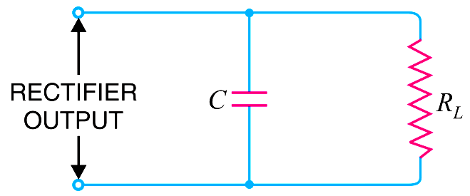
Capacitor filter. Fig. shows a typical capacitor filter circuit. It consists of a capacitor C placed across the rectifier output in parallel with load RL. The pulsating direct voltage of the rectifier is applied across the capacitor. As the rectifier voltage increases, it charges the capacitor and also supplies current to the load.
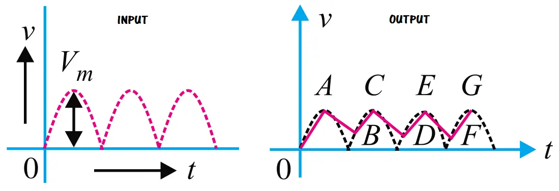
At the end of quarter cycle [Point A in Fig.], the capacitor is charged to the peak value Vm of the rectifier voltage. Now, the rectifier voltage starts to decrease. As this occurs, the capacitor discharges through the load and voltage across it (i.e. across parallel combination of R–C) decreases as shown by the line AB in Fig. The voltage across load will decrease only slightly because immediately the next voltage peak comes and recharges the capacitor. This process is repeated again and again and the output voltage waveform becomes ABCDEFG. It may be seen that very little ripple is left in the output. Moreover, output voltage is higher as it remains substantially near the peak value of rectifier output voltage.
The capacitor filter circuit is extremely popular because of its low cost, small size, little weight and good characteristics. For small load currents, this type of filter is preferred.