Inst ToolsInst ToolsInst Tools
  • Courses
  • Automation
    • PLC
    • Control System
    • Safety System
    • Communication
    • Fire & Gas System
  • Instrumentation
    • Design
    • Pressure
    • Temperature
    • Flow
    • Level
    • Vibration
    • Analyzer
    • Control Valve
    • Switch
    • Calibration
    • Erection & Commissioning
  • Interview
    • Instrumentation
    • Electrical
    • Electronics
    • Practical
  • Q&A
    • Instrumentation
    • Control System
    • Electrical
    • Electronics
    • Analog Electronics
    • Digital Electronics
    • Power Electronics
    • Microprocessor
  • Request
Search
  • Books
  • Software
  • Projects
  • Process
  • Tools
  • Basics
  • Formula
  • Power Plant
  • Root Cause Analysis
  • Electrical Basics
  • Animation
  • Standards
  • 4-20 mA Course
  • Siemens PLC Course
Reading: Y and Delta Resistor Network Calculations
Share
Font ResizerAa
Inst ToolsInst Tools
Font ResizerAa
  • Courses
  • Design
  • PLC
  • Interview
  • Control System
Search
  • Courses
  • Automation
    • PLC
    • Control System
    • Safety System
    • Communication
    • Fire & Gas System
  • Instrumentation
    • Design
    • Pressure
    • Temperature
    • Flow
    • Level
    • Vibration
    • Analyzer
    • Control Valve
    • Switch
    • Calibration
    • Erection & Commissioning
  • Interview
    • Instrumentation
    • Electrical
    • Electronics
    • Practical
  • Q&A
    • Instrumentation
    • Control System
    • Electrical
    • Electronics
    • Analog Electronics
    • Digital Electronics
    • Power Electronics
    • Microprocessor
  • Request
Follow US
All rights reserved. Reproduction in whole or in part without written permission is prohibited.
Inst Tools > Blog > Electrical Theory > Y and Delta Resistor Network Calculations

Y and Delta Resistor Network Calculations

Last updated: July 25, 2018 7:20 pm
Editorial Staff
Electrical Theory
No Comments
Share
3 Min Read
SHARE

Because of its shape, the network shown in Figure 47 is called a T (tee) or Y (wye) network.

These are different names for the same network.

T or Y Network

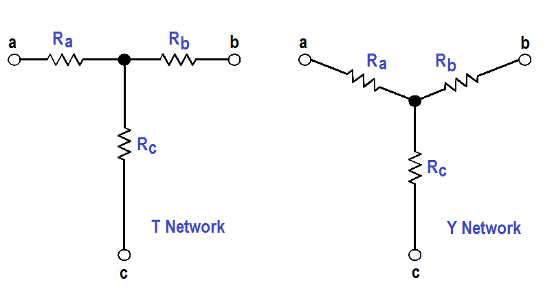
Figure 47 : T or Y Network

The network shown in Figure 48 is called π (pi) or ∆ (delta) because the shapes resemble Greek letters π and Ω. These are different names for the same network.

π (pi) or ∆ (delta) Network

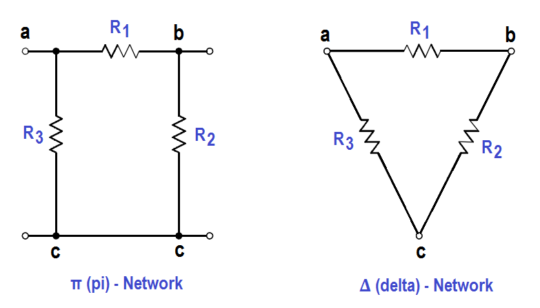
Figure 48 : π (pi) or ∆ (delta) Network

In order to analyze the circuits, it may be helpful to convert Y to ∆,or ∆ to Y, to simplify the solution. The formulas that will be used for these conversions are derived from Kirchhoff’s laws.

The resistances in these networks are shown in a three-terminal network. After we use the conversion formulas, one network is equivalent to the other because they have equivalent resistances across any one pair of terminals (Figure 49).

∆ to Y conversion:

∆ to Y conversion Formulas

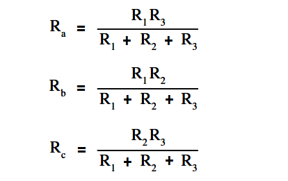
Rule 1: The resistance of any branch of a Y network is equal to the product of the two adjacent sides of a ∆ network, divided by the sum of the three ∆ resistances.

Y - ∆ Equivalent of Resistor Network

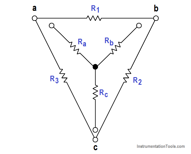
Figure 49 : Y – ∆ Equivalent

Y to ∆ conversion:

Y - ∆ Equivalent of Resistor network formula

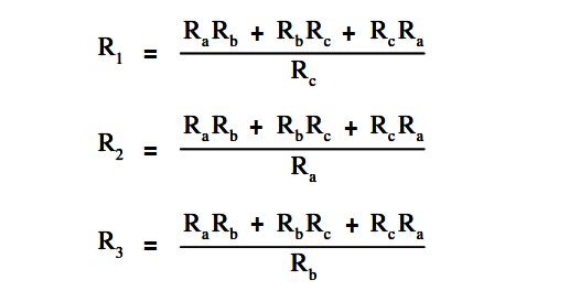
Rule 2: The resistance of any side of a ∆ network is equal to the sum of the Y network resistance, multiplied in pairs, divided by the opposite branch of the Y network.

Let us consider a bridge circuit (Figure 50).

Resistor Delta Network

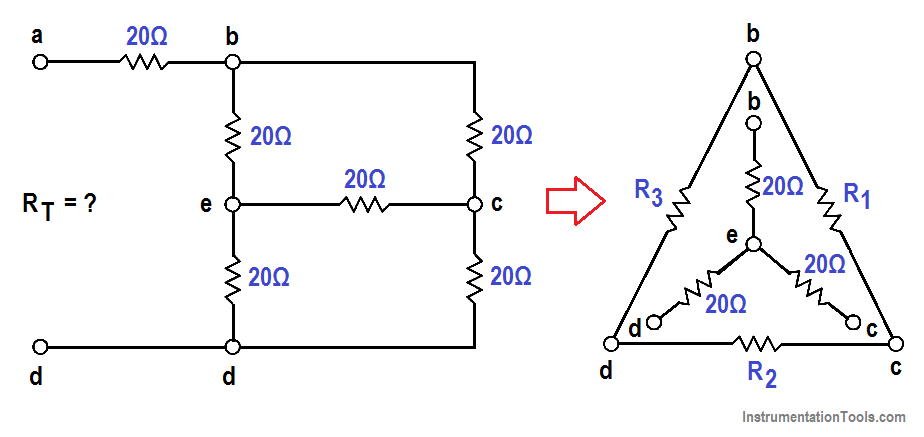
Figure 50 : Bridge Circuit

Find Rt at terminals a and d.

Step 1: Convert the Y network (b-e, e-c, e-d) to the equivalent ∆ network.

Using Rule 2:

R1 = { (20×20) + (20×20) + (20×20) } / 20 = 1200/20 = 60Ω

R2 = 1200/20 = 60Ω

R3 = 1200/20 = 60Ω

Step 2: Now, we can redraw the Y circuit as a ∆ circuit and reconnect it to the original circuit (Figure 51):

Y - ∆ Redrawn Resistor Circuit

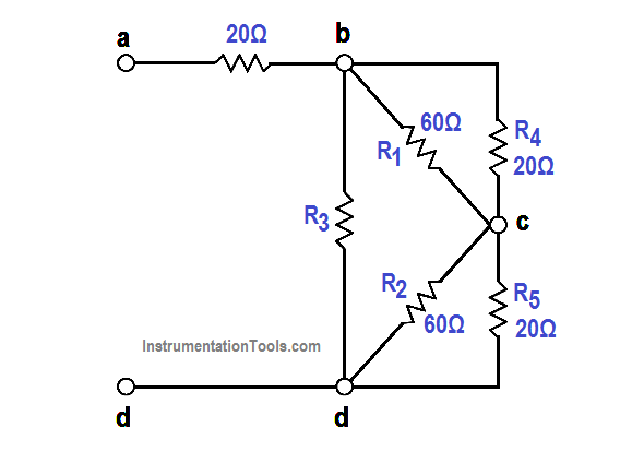
Figure 51 : Y – ∆ Redrawn Circuit

Step 3: Reduce and simplify the circuit. Note that the 20Ω and 60Ω branches are in parallel in Figure 51. Refer to Figures 51 and 52 for redrawing the circuit in each step below.

Rp = (R1R4) / (R1 + R4) = (20×60) / (20+60) = 1200/80 = 15Ω

Rq = (R1R5) / (R1 + R5) = (20×60) / (20+60) = 1200/80 = 15Ω

Rr = [ R3(Rp + Rq) ] / [R3 +Rp+Rq] = [60x(15+5)] / [60+30] = 1800/90 = 20Ω

RT = 20 + 20 = 40Ω

Resistor Y and Delta Network Calculation

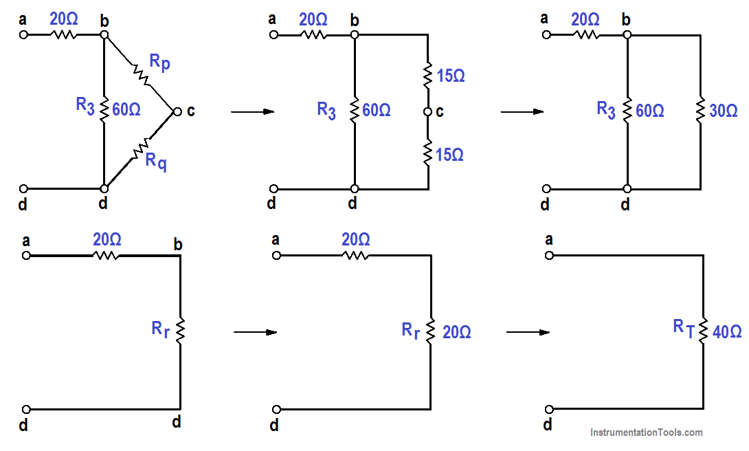
Figure 52 : Steps to Simplify Redrawn Circuit

Don't Miss Our Updates
Be the first to get exclusive content straight to your email.
We promise not to spam you. You can unsubscribe at any time.
Invalid email address
You've successfully subscribed !

Continue Reading

Compound Generators
DC Motor Torque
Starting of DC Motors
Applying Kirchhoff’s Current Law
Electrical System Components and Protection Devices
DC Generator Theory
Share This Article
Facebook Whatsapp Whatsapp LinkedIn Copy Link
Share
Leave a Comment

Leave a Reply Cancel reply

Your email address will not be published. Required fields are marked *

Stay Connected

128.3kFollowersLike
69.1kFollowersFollow
210kSubscribersSubscribe
38kFollowersFollow

Categories

Explore More

Shunt-Wound DC Generators
AC Generator Theory
Starting a Synchronous Motor
What is Synchroscope ?
AC Generation
Calculate Power in Parallel RC Circuit
DC Machines Construction
Synchronous Motors

Keep Learning

Schematic Diagram

Schematic Diagram

Auto Transformer Schematic

Classification of Transformers

Calculate Power in Parallel RCL Circuit

Calculate Power in Parallel RCL Circuit

Phase angle

AC Generation Analysis : Effective Values, Phase Angle and Frequency

Thermoelectricity principle

Methods of Producing Voltage (Electricity)

Cutaway View of Circuit Breaker

Low Voltage Air Circuit Breaker Principle

Units of Electrical Measurement

Units of Electrical Measurement

Capacitors Connected in Parallel

Series and Parallel Capacitors

Learn More

DC Motors Objective Questions and Answers

175+ DC Motors Objective Questions and Answers

Measure Capacitance using Multimeter

How to Measure capacitance using Multimeter

Nameplate Markings

Explosive Atmospheres & Hazardous Classification

As-found and As-left Calibration

As-found and As-left Documentation during Calibration

DCS System Layout and its Different Parts

DCS System Layout and its Different Parts

PLC Program

Example PLC Program

Solve Pressure Control System Problems

Pressure Control System Problems

How to Calculate Network Speed?

Factors to Consider When Calculating Network Speed

Menu

  • About
  • Privacy Policy
  • Copyright

Quick Links

  • Learn PLC
  • Helping Hand
  • Part Time Job

YouTube Subscribe

Follow US
All rights reserved. Reproduction in whole or in part without written permission is prohibited.
Welcome Back!

Sign in to your account

Username or Email Address
Password

Lost your password?