Inst ToolsInst ToolsInst Tools
  • Courses
  • Automation
    • PLC
    • Control System
    • Safety System
    • Communication
    • Fire & Gas System
  • Instrumentation
    • Design
    • Pressure
    • Temperature
    • Flow
    • Level
    • Vibration
    • Analyzer
    • Control Valve
    • Switch
    • Calibration
    • Erection & Commissioning
  • Interview
    • Instrumentation
    • Electrical
    • Electronics
    • Practical
  • Q&A
    • Instrumentation
    • Control System
    • Electrical
    • Electronics
    • Analog Electronics
    • Digital Electronics
    • Power Electronics
    • Microprocessor
  • Request
Search
  • Books
  • Software
  • Projects
  • Process
  • Tools
  • Basics
  • Formula
  • Power Plant
  • Root Cause Analysis
  • Electrical Basics
  • Animation
  • Standards
  • 4-20 mA Course
  • Siemens PLC Course
Reading: Wiring Diagram
Share
Font ResizerAa
Inst ToolsInst Tools
Font ResizerAa
  • Courses
  • Design
  • PLC
  • Interview
  • Control System
Search
  • Courses
  • Automation
    • PLC
    • Control System
    • Safety System
    • Communication
    • Fire & Gas System
  • Instrumentation
    • Design
    • Pressure
    • Temperature
    • Flow
    • Level
    • Vibration
    • Analyzer
    • Control Valve
    • Switch
    • Calibration
    • Erection & Commissioning
  • Interview
    • Instrumentation
    • Electrical
    • Electronics
    • Practical
  • Q&A
    • Instrumentation
    • Control System
    • Electrical
    • Electronics
    • Analog Electronics
    • Digital Electronics
    • Power Electronics
    • Microprocessor
  • Request
Follow US
All rights reserved. Reproduction in whole or in part without written permission is prohibited.
Inst Tools > Blog > Electrical Theory > Wiring Diagram

Wiring Diagram

Last updated: July 23, 2018 10:12 am
Editorial Staff
Electrical Theory
No Comments
Share
1 Min Read
SHARE

 A wiring diagram is a very simple way to show wiring connections in an easy-to-follow manner. These types of diagrams are normally found with home appliances and automobile electrical systems (Figure 12).

Wiring diagrams show the component parts in pictorial form, and the components are identified by name. Most wiring diagrams also show the relative location of component parts and color coding of conductors or leads.

Wiring Diagram

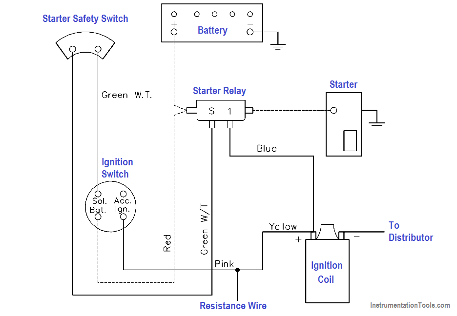
Figure 12 Wiring Diagram

Don't Miss Our Updates
Be the first to get exclusive content straight to your email.
We promise not to spam you. You can unsubscribe at any time.
Invalid email address
You've successfully subscribed !

Continue Reading

DC Motor Connections
Resistivity
How to Measure Specific Gravity of Battery
Low Voltage Air Circuit Breaker Principle
Three Phase Systems
Three Phase Transformer Connections
Share This Article
Facebook Whatsapp Whatsapp LinkedIn Copy Link
Share
Leave a Comment

Leave a Reply Cancel reply

Your email address will not be published. Required fields are marked *

Stay Connected

128.3kFollowersLike
69.1kFollowersFollow
210kSubscribersSubscribe
38kFollowersFollow

Categories

Explore More

Power in Balanced 3 Phase Loads
Parallel Short Circuit Faults
Calculate Power in Series RCL Circuit
Types of Capacitors
DC Motor Theory
Voltage Divider
Calculate Power in Series RC Circuit
Capacitance

Keep Learning

Electrical Symbols

Electrical Symbols

Generator Action in a Motor

Generator Action in a Motor

Potential Difference Across a Conductor Causes a Current to Flow

Conductor, Insulator, Resistor and Current Flow

Transformer Coil Polarity

Transformer Coil Polarity

Using Kirchhoff’s Voltage Law to find Current with Multiple Battery Sources

Kirchhoff’s Laws

Squirrel-Cage Induction Rotor

Induction Motor

Thermocouples

Thermocouples

DC Generator

DC Generator

Learn More

Bellow Principle

Bellows

Burnout Function in Temperature Transmitter

Burnout Function in Temperature Transmitter

Capillary Remote Seal Leave Measurement

Siemens Pressure Transmitter with Remote Seals Calculations

Power Electronics Objective Questions

PWM based Inverters in Power Electronics Quiz

3 Way Circuit Animation

Three Way Electrical Switch Working Animation

difference between invasive and non-invasive and intrusive and non-intrusive

Difference between Invasive, Non-invasive, Intrusive & Non-intrusive

Connect the Differential Pressure Gauge at the Filter

How Do You Connect the Differential Pressure Gauge at the Filter?

Relay Principle

Advantages & Disadvantages Electromagnetic Relays

Menu

  • About
  • Privacy Policy
  • Copyright

Quick Links

  • Learn PLC
  • Helping Hand
  • Part Time Job

YouTube Subscribe

Follow US
All rights reserved. Reproduction in whole or in part without written permission is prohibited.
Welcome Back!

Sign in to your account

Username or Email Address
Password

Lost your password?