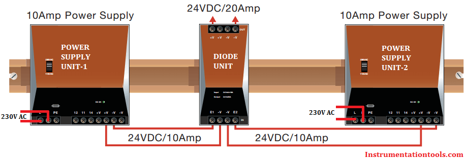
The Diode module can be used to 100% decouple two power supplies of the same type, which are connected in parallel on the output side to increase power or provide redundancy.
Diode protection for a DC power supply is a critical piece of a control system. Power supply failure can lead to a process shutting down resulting in considerable lost revenue.
To prevent unplanned shutdowns users often use redundant power supplies, i.e. power supplies with their outputs connected in parallel, where if one supply fails there are enough remaining power supplies to deliver the required load current.

Redundant power supplies can be also be used for increased current capacity – in this case the concern is less about unplanned shutdowns but rather the fact one supply cannot deliver the load current required.
For increased current capacity power supplies with “active load sharing” are preferred. This involves the power supplies communicating with each other and adjusting their output voltages so that each supply delivers the same current.
If two supplies are used each one will deliver half the required current. If three supplies are used each one delivers a third of the total current required.
Without active load sharing each power supply must be adjusted so that their output voltages are identical, they much be maintained at the same ambient temperature and the wiring between each power supply and the common point should be of equal lengths – all difficult conditions to maintain.
Regardless of the reason for using redundant power supplies it is common practice to provide diode protection in series with the output of each power supply so a failed power supply cannot draw current from any operating power supplies.
If there is a short circuit in the output of a power supply that unit will shutdown but it could also short circuit any power supplies connected in parallel causing those to shutdown as well.
A diode on the output of each supply prevents this from happening.
Using diodes to isolate power supplies, often referred to as “ORing diodes”, has the disadvantage of increasing power dissipation within the control cabinet.
A typical diode drops the voltage 0.7V when conducting a current. This means 0.7W per amp of load current. If two redundant power supplies are delivering a total of 10A then the diodes will dissipate 7W in the cabinet. Using Schottky diodes could lower the power dissipation to approximately 4W.
Either way, this power dissipation is unwanted and increases the ambient temperature within the cabinet. Sometimes bridge rectifiers are used because they are relatively inexpensive, are designed for high power dissipation, and can be mounted directly on the wall of the cabinet so that the cabinet acts as a heat sink.
Reliability is a concern (or should be) when using ORing diodes. If a diode fails in a short circuited state then there is no protection and the voltage from that supply appears to increase by 0.7V.
Unless active load sharing is used that supply may try to deliver the total load current. If the power supplies are connected in parallel for increased current capacity then the supply might go in to an overcurrent condition and shutdown.
If one of the ORing diodes fails in an open circuit state then there is no longer any redundancy and a shutdown of thr remaining power supply could occur.
An option is to use an active diode circuit. These are based on using a MOSFET, with additional circuitry, in place of the diode. MOSFET’s have the advantage of a very low on-state resistance meaning the power dissipation is reduced significantly.
For example, at 10A a diode will dissipate 7W while the MOSFET based active diode circuit can dissipate as little as 0.4W. Obviously this produces a lower ambient temperature within the cabinet and also offers greater reliability.
Also Read: Pull Up and Pull Down Switch
In this article, a simple example will teach you the conversion from Boolean algebra to…
In this article, you will learn the PLC cooking timer example for kitchen automation using…
Learn an example PLC program to control a pump based on level sensors using ladder…
In the PLC timer application for security camera recording, when motion is detected then camera…
In this example, we will learn batch mixing with PLC ladder logic program using timer…
This PLC example on manufacturing line assembly is an intermediate-level PLC program prepared for the…
View Comments
Good Article
thanks
I have heard that once a diode oring is implemented, load sharing between power supplies do not work. I am not able to correlate this or find any data which supports this statement. Can anyone help me out to say if this is true or not?
There is one more instruments site can someone upload the link that is Instreng.co.in something like this where there is good information.Thanks
Instreng.com is a community platform for instrumentation engineers, very knowledgeable source. Few months ago it was hacked and now we missed it a lot. Recently Inst Tools also hacked & luckily i have a backup of the website & immediately restored. Hope everything will be fine.
Sir, please post about field interfere module. D