In this post, we will cover the basic concepts of solid state relay.
One of the most important components used in an electrical panel is a relay. Mostly, people are familiar with standard electromechanical relays.
But, there is another type of relay which is also used widely for a large variety of loads – mainly heavy and resistive types. This is a solid state relay (SSR). In this post, we will understand the basic concept of a solid state relay.
As the name implies, solid state relay (SSR) works on semiconductors. In contrast to an electromechanical relay which uses mechanical contacts to switch on or off a circuit, there are no mechanical contacts inside the solid state relay.
Switching is done swiftly through semiconductors like triac, transistor, diode, and thyristors. The technique works on either infrared light emitting diodes or LED couplers to operate. Due to the use of semiconductors, the switching is very fast as compared to a standard electromechanical relay.
Also, you can get a wide variety of control voltage from SSR, either fixed or variable, due to the use of semiconductors. The solid state relay is mostly used for resistive and heavy loads like heaters and heat tracings, which require a large amount of load current.
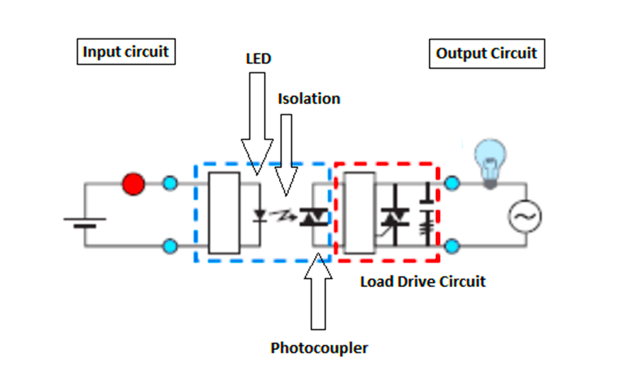
Refer to the below figure. As discussed before, solid state relay (SSR) does not have moving parts. They consist of semiconductors and electronic parts.

The input circuit consists of a LED which is triggered by the input voltage. Then, there is isolation between input and output circuits.
The output circuit consists of a photo-coupler for capturing the light and converting it into electrical energy for the load drive circuit (consisting of either triac, diodes, transistors, or thyristors).
When the power supply is applied to the input circuit, current flows through LED which emits light from it. The photo-coupler detects it and converts it into an electrical voltage which is then fed to the load drive circuit, for controlling the final output voltage to the load. When the input voltage turns off, the load too turns off.
Due to the use of Opto-coupling technology, the switching is swift, sensitive, and has high insulation levels. The output voltage can be digital or analog, depending upon the input circuit and load drive circuit used.
There are three types of control methods available for solid state relays (SSR).
They are as follows
When the input voltage is applied as shown in the figure, the output voltage immediately turns on and is applied for the whole AC cycle as long as the input voltage is on.
As soon as it turns off, the output voltage also turns off.
As shown in the figure below, when the input voltage is applied, the output voltage does not immediately turn on; rather it starts the cycle as soon as it touches the next available zero point in the waveform.
Then, it is applied for the whole AC cycle as long as the input voltage is on. When the input voltage is released, the output voltage does not immediately turn off; rather it stops the cycle as soon as it touches the next available zero point in the waveform.
The earlier two types we discussed were digital output types. As the name implies, proportional control solid state relay provides an analog output.
According to the input voltage given, the output voltage will be given accordingly. This type is used for PID control of heaters and other devices, where accurate control of temperature is required.
In this way, we saw the concept of solid state relay, and it is widely used in many types of loads.
If you liked this article, then please subscribe to our YouTube Channel for Instrumentation, Electrical, PLC, and SCADA video tutorials.
You can also follow us on Facebook and Twitter to receive daily updates.
Read Next:
Learn the example of flip-flop PLC program for lamps application using the ladder logic to…
In this article, you will learn the STAR DELTA programming using PLC controller to start…
Lube oil consoles of rotary equipment packages in industrial process plants are usually equipped with…
Rotating equipment packages such as pumps, compressors, turbines need the lube oil consoles for their…
This article explains how to blink lights in ladder logic with a detailed explanation video…
In this article, a simple example will teach you the conversion from Boolean algebra to…