Inst ToolsInst ToolsInst Tools
  • Courses
  • Automation
    • PLC
    • Control System
    • Safety System
    • Communication
    • Fire & Gas System
  • Instrumentation
    • Design
    • Pressure
    • Temperature
    • Flow
    • Level
    • Vibration
    • Analyzer
    • Control Valve
    • Switch
    • Calibration
    • Erection & Commissioning
  • Interview
    • Instrumentation
    • Electrical
    • Electronics
    • Practical
  • Q&A
    • Instrumentation
    • Control System
    • Electrical
    • Electronics
    • Analog Electronics
    • Digital Electronics
    • Power Electronics
    • Microprocessor
  • Request
Search
  • Books
  • Software
  • Projects
  • Process
  • Tools
  • Basics
  • Formula
  • Power Plant
  • Root Cause Analysis
  • Electrical Basics
  • Animation
  • Standards
  • 4-20 mA Course
  • Siemens PLC Course
Reading: Venturi Flow Meter – Working Principle, Advantages, Animation
Share
Notification Show More
Font ResizerAa
Inst ToolsInst Tools
Font ResizerAa
  • Courses
  • Design
  • PLC
  • Interview
  • Control System
Search
  • Courses
  • Automation
    • PLC
    • Control System
    • Safety System
    • Communication
    • Fire & Gas System
  • Instrumentation
    • Design
    • Pressure
    • Temperature
    • Flow
    • Level
    • Vibration
    • Analyzer
    • Control Valve
    • Switch
    • Calibration
    • Erection & Commissioning
  • Interview
    • Instrumentation
    • Electrical
    • Electronics
    • Practical
  • Q&A
    • Instrumentation
    • Control System
    • Electrical
    • Electronics
    • Analog Electronics
    • Digital Electronics
    • Power Electronics
    • Microprocessor
  • Request
Follow US
All rights reserved. Reproduction in whole or in part without written permission is prohibited.
Inst Tools > Blog > Animation > Venturi Flow Meter – Working Principle, Advantages, Animation

Venturi Flow Meter – Working Principle, Advantages, Animation

When venturi flow meter is placed in a pipe carrying the fluid whose flow rate is to be measured, a pressure drop occurs across venturi meter.

Last updated: October 31, 2023 4:59 pm
Editorial Staff
Animation Flow Measurement
1 Comment
Share
5 Min Read
SHARE

When a venturi flow meter is placed in a pipe carrying the fluid whose flow rate is to be measured, a pressure drop occurs between the entrance and throat of the venturi meter.

Contents
Venturi Flow MeterConstruction of Venturi meterOperation of Venturi MeterApplications of Venturi MetersAdvantages of Venturi MetersLimitations of Venturi Meters

This pressure drop is measured using a differential pressure sensor and when calibrated this pressure drop becomes a measure of flow rate.

Venturi Flow Meter

The below animations shows the working of venturi flow meter.
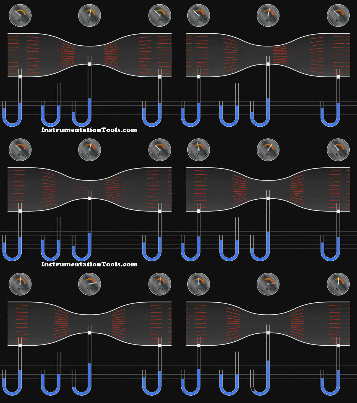
Venturi Flow Meter Working Animation

Construction of Venturi meter

The following are the main parts and areas of the venturi meter:
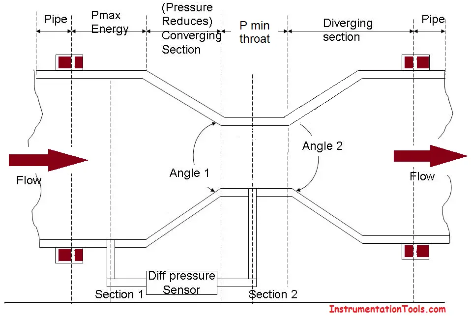
Construction of Venturi meter

The entry of the venture is cylindrical in shape to match the size of the pipe through which fluid flows. This enables the venture to be fitted to the pipe.

After the entry, there is a converging conical section with an included angle of 19’ to 23’.

Following the converging section, there is a cylindrical section with a minimum area called as the throat.

After the throat, there is a diverging conical section with an included angle of 5’ to 15’.

Openings are provided at the entry and throat (at sections 1 and 2 in the diagram) of the venture meter for attaching a differential pressure sensor (u-tube manometer, differential pressure gauge, etc) as shown in the diagram.

Operation of Venturi Meter

The fluid whose flow rate is to be measured enters the entry section of the venturi meter with a pressure P1.

As the fluid from the entry section of venturi meter flows into the converging section, its pressure keeps on reducing and attains a minimum value P2 when it enters the throat. That is, in the throat, the fluid pressure P2 will be minimal.
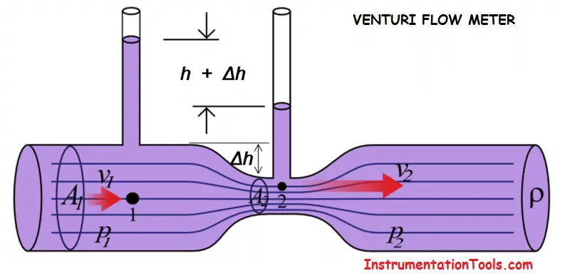
Venturi Flow Meter

The differential pressure sensor attached between the entry and throat section of the venturi meter records the pressure difference(P1-P2) which becomes an indication of the flow rate of the fluid through the pipe when calibrated.

The diverging section has been provided to enable the fluid to regain its pressure and hence its kinetic energy. The lower the angle of the diverging section, the greater the recovery.

Applications of Venturi Meters

  • It is used where high-pressure recovery is required.
  • Can be used for measuring flow rates of water, gases, suspended solids, slurries, and dirty liquids.
  • Can be used to measure high flow rates in pipes having diameters in a few meters.

Advantages of Venturi Meters

  • Fewer changes of getting clogged with sediments
  • The coefficient of discharge is high.
  • Its behavior can be predicted perfectly.
  • Can be installed vertically, horizontally, or inclined.
  • Low-pressure drop (around 10% of Δp)
  • Lower sensitivity to installation effects than orifice plates
  • Less susceptibility to damage
  • More suitable for gas flows with entrained liquid
  • Comprehensive standards (ISO 5167)

Limitations of Venturi Meters

  • They are large in size and hence where space is limited, they cannot be used.
  • Expensive initial cost, installation, and maintenance.
  • Require long laying length. That is, the venturi meter has to be proceeded by a straight pipe which is free from fittings and misalignments to avoid turbulence in flow, for satisfactory operation. Therefore, straightening vanes is a must.
  • Low turndown (can be improved with dual range Δp cells)
  • Greater cost to manufacture
  • Greater susceptibility to “tapping errors” in high Reynolds number gas flows owing to the high-velocity fluid passing the pressure tapping at the throat.
  • Less experimental data than orifice plates

If you liked this article, then please subscribe to our YouTube Channel for Instrumentation, Electrical, PLC, and SCADA video tutorials.

You can also follow us on Facebook and Twitter to receive daily updates.

Read Next:

  • Basics of Venturi Flow Meter
  • What is Averaging Pitot Tube
  • Strain Gauge Pressure Sensor
  • How Orifice Measures Flow
  • 3-15 psi to 4-20mA Convert
Don't Miss Our Updates
Be the first to get exclusive content straight to your email.
We promise not to spam you. You can unsubscribe at any time.
Invalid email address
You've successfully subscribed !

Continue Reading

Resistor Color Code Animation
Particle Image Velocimetry (PIV) Principle
Four Way Solenoid Valve Working Principle
Magnetic Level Indicators Working Animation
Transit Time Flow Meter Principle
PID Controller Gains Effect on Manipulated Variable
Share This Article
Facebook Whatsapp Whatsapp LinkedIn Copy Link
Share
1 Comment
  • George Achakpo says:
    June 3, 2023 at 8:05 am

    Its educative.
    Thanks,
    From Emgr G.C. Achakpo

    Reply

Leave a Reply Cancel reply

Your email address will not be published. Required fields are marked *

Stay Connected

128.3kFollowersLike
69.1kFollowersFollow
210kSubscribersSubscribe
38kFollowersFollow

Categories

Explore More

Relay Principle & its Types
Magnetic Flowmeter vs. Turbine Flowmeter – Comparison
What is a Torbar? – Averaging Pitot Tubes
Target Flow Meter – Working Principle, Advantages, Disadvantages
Thermal Dispersion Flow Switch Working Principle
What is a Condensate Pot? How to Install it?
Transit Time Flow Meter – Types, Advantages, Disadvantages
Vibrating Tube Densitometers Working Principle

Keep Learning

Annubar flow principle

Different Types of Flow Elements

Beam-Detectors-Working-Principle-2

Beam Detectors Working Principle Animation

Sutro weir flow meter principle

Weirs and Flumes Flow Measurement

pressure-gauge-animation

Bourdon Tube Pressure Gauge Working Principle Animation

Flow Meter Hook Up

Flow Meter Installation Guidelines

Coriolis Mass Flow Meter Verification Procedure

Prover Tank Calibration and Mass Flow Meter Verification Procedure

Level Measurement using DP Transmitters - Open Tank

Open Tank Level Measurement using DP Transmitters Animation

Classic Control Circuits

Motor Classic Control Circuits using Single Push button

Learn More

Deluge Valve Operation using Solenoid Valve Animation

Deluge Valve Operation

Start the Counting from a Preset Value in PLC

Start the Counting from a Preset Value in PLC

Power Electronics Objective Questions

Type D Chopper Objective Questions

Basics of FOUNDATION Fieldbus

Difference between Fieldbus, Profibus and HART Protocols

Valve Leakage Tests

Types of Valve Leakage Tests

Velocity-based Flowmeter

What is a Velocity-based Flow Meter?

Remote Diaphragm Seal Transmitter for Vacuum Application

Remote Diaphragm Seal Transmitter for Vacuum Application

Instrumentation Standards

Menu

  • About
  • Privacy Policy
  • Copyright

Quick Links

  • Learn PLC
  • Helping Hand
  • Part Time Job

YouTube Subscribe

Follow US
All rights reserved. Reproduction in whole or in part without written permission is prohibited.
Welcome Back!

Sign in to your account

Username or Email Address
Password

Lost your password?