Inst ToolsInst ToolsInst Tools
  • Courses
  • Automation
    • PLC
    • Control System
    • Safety System
    • Communication
    • Fire & Gas System
  • Instrumentation
    • Design
    • Pressure
    • Temperature
    • Flow
    • Level
    • Vibration
    • Analyzer
    • Control Valve
    • Switch
    • Calibration
    • Erection & Commissioning
  • Interview
    • Instrumentation
    • Electrical
    • Electronics
    • Practical
  • Q&A
    • Instrumentation
    • Control System
    • Electrical
    • Electronics
    • Analog Electronics
    • Digital Electronics
    • Power Electronics
    • Microprocessor
  • Request
Search
  • Books
  • Software
  • Projects
  • Process
  • Tools
  • Basics
  • Formula
  • Power Plant
  • Root Cause Analysis
  • Electrical Basics
  • Animation
  • Standards
  • 4-20 mA Course
  • Siemens PLC Course
Reading: Valve Position Indication
Share
Font ResizerAa
Inst ToolsInst Tools
Font ResizerAa
  • Courses
  • Design
  • PLC
  • Interview
  • Control System
Search
  • Courses
  • Automation
    • PLC
    • Control System
    • Safety System
    • Communication
    • Fire & Gas System
  • Instrumentation
    • Design
    • Pressure
    • Temperature
    • Flow
    • Level
    • Vibration
    • Analyzer
    • Control Valve
    • Switch
    • Calibration
    • Erection & Commissioning
  • Interview
    • Instrumentation
    • Electrical
    • Electronics
    • Practical
  • Q&A
    • Instrumentation
    • Control System
    • Electrical
    • Electronics
    • Analog Electronics
    • Digital Electronics
    • Power Electronics
    • Microprocessor
  • Request
Follow US
All rights reserved. Reproduction in whole or in part without written permission is prohibited.
Inst Tools > Blog > Control Valves > Valve Position Indication

Valve Position Indication

Last updated: March 21, 2019 3:24 pm
Editorial Staff
Control Valves
No Comments
Share
1 Min Read
SHARE

Operators require indication of the position of certain valves to permit knowledgeable operation of the plant.

For such valves, remote valve position indication is provided in the form of position lights that indicate if valves are open or closed.

Valve Position Indication

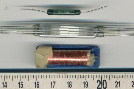
Remote valve position indication circuits use a position detector that senses stem and disk position or actuator position. One type of position detector is the mechanical limit switch, which is physically operated by valve movement.

Another type is magnetic switches or transformers that sense movement of their magnetic cores, which are physically operated by valve movement.
Valve Position Indication

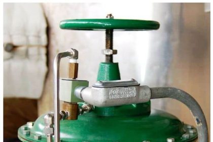
Local valve position indication refers to some visually discernable characteristic of the valve that indicates valve position.

Rising stem valve position is indicated by the stem position.

Non-rising stem valves sometimes have small mechanical pointers that are operated by the valve actuator simultaneously with valve operation.

Power actuated valves typically have a mechanical pointer that provides local valve position indication.

On the other hand, some valves do not have any feature for position indication.
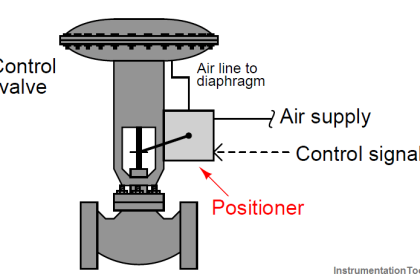
Articles You May Like :

Actuators Questions and Answers

Electronic Valve positioners

Dampers and Louvres

Butterfly Check Valves

Air Lock Relay Principle

Don't Miss Our Updates
Be the first to get exclusive content straight to your email.
We promise not to spam you. You can unsubscribe at any time.
Invalid email address
You've successfully subscribed !

Continue Reading

Thermostatic Valves Working Principle
Direct Lift Diaphragm Solenoid Valve Principle
Control Valve Characteristics
Rotary Stem Valves
What is Pinch Valve ?
How is Pressure Drop Calculated through a Valve ?
Share This Article
Facebook Whatsapp Whatsapp LinkedIn Copy Link
Share
Leave a Comment

Leave a Reply Cancel reply

Your email address will not be published. Required fields are marked *

Stay Connected

128.3kFollowersLike
69.1kFollowersFollow
210kSubscribersSubscribe
38kFollowersFollow

Categories

Explore More

Classification of Control Valves
Fundamentals of Valves and their Types
Control Valve Relation between Cv and Kv
How Pilot operated Solenoid Valve Works ?
Control Valves Leakage Classifications
Control Valve Stroke Test Procedure
What is an Actuator? – Different Types of Actuators
Control Valve Preventive Maintenance

Keep Learning

How to Protect Pumps from Cavitation

How to Protect Pumps from Cavitation? – Reasons, Solutions

Difference between Rotary Shaft and Sliding Stem Control Valves

Difference between Rotary Shaft Valves and Sliding Stem Control Valves

How to Remove Control Valve Stem Packing Procedure

The Replacement Procedure for Control Valve Stem Packing

Purpose of Float Valve

What is a Float Control Valve? Types, Advantages, Disadvantages

Control Valve Air to Open type

Control Valve Installation, Maintenance, Disassembly & Reassembly

Basic Configuration of Motor Operated Valve

Rotork Motor Operated Valve Basic Configuration

Control Valves Multiple Choice Questions

Control Valves Multiple Choice Questions

Difference Between Solenoid Valve and Motorized Valve

Difference Between Solenoid Valve and Motorized Valve

Learn More

Captive Power Plant Trip Root Cause Analysis

Captive Power Plant Trip Root Cause Analysis

Causes of PLC Stop Mode

Various Causes for PLC Going in Stop Mode

Rupture disks

Rupture disks

3-15 psi to 4-20mA Conversion

Example of 3-15 psi to 4-20mA Conversion

Single Port Globe Valve

How Sliding Stem Valves Work ?

Pressure to Current Converter

Pressure to Current (P/I) Converter Principle

Bio Sensors Objective Questions

Bio Sensors Objective Questions

Stability in Frequency Domain

The Design Problem

Menu

  • About
  • Privacy Policy
  • Copyright

Quick Links

  • Learn PLC
  • Helping Hand
  • Part Time Job

YouTube Subscribe

Follow US
All rights reserved. Reproduction in whole or in part without written permission is prohibited.
Welcome Back!

Sign in to your account

Username or Email Address
Password

Lost your password?