To study the working of Up Counter PLC program in Allen Bradley Programmable Logic Controller (PLC).
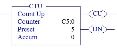
In the above picture, there are totally three parameter,
COUNTER: C4:0 – Counter File name (Timer C5:0, C5:1, C5:2…)
PRESET –PRE: Limit value of COUNT-Up to how much it should count
ACCUMULATOR –ACC: Running Value of counter when condition turn ON.
From the data file, along with preset and accumulator, we have few more bits,
CU: Count up Bit-whenever the counter is enable makes this bit to go ON.
DN: Done Bit-When accumulator value reached preset value, done bit turns to ON.
OV: Over Flow Bit-When accumulator value reached the limit value (32767),it rolls back to
-32767 for the upcoming counter operation, Overflow bit turns ON, in this condition.
Notes:
UA-Update Accumulator Value-Only used when high speed counters are used in the program.
CD & UN-Used for down Counter Function.
I:0/0 is used to give input to counter and Preset value is set to 5.
In the below Ladder logic,
Rung 000 – Having condition input I:0/0 which gives input to counter to perform counter function.
Rung 0001 – Having Counter CU Bit which enable only when counter is in function or When input to the counter turns ON.
In the below ladder Logic,
When input to the counter turn OFF (I:0/0),Counter CU bit turns OFF. Output O:0/0 turns ON only when C5:0/CU turns ON.
In the Below Ladder Logic,
When accumulator value reaches the Preset, Counter Done bit (Cu5:0/DN) turns ON.
In the below ladder Logic,
Done bits remains in the ON condition, even though accumulator value runs beyond Preset.
In the Below Ladder Logic,
Counter accumulator value overflows when accumulator value reaches 32767 in Allen Bradley PLC Programming.
In the below ladder Logic,
When we turn ON the I:0/0 for the 32768 time,accumulator value rolls back to -32768 and start counting from -32767 to 32767.Counter Overflow bit turns ON when this condition happen (Rung 003).
We can use this explanation to understand the working of Up Counter function in Allen Bradley Programmable Logic Controller (PLC).
If you liked this article, then please subscribe to our YouTube Channel for PLC and SCADA video tutorials.
You can also follow us on Facebook and Twitter to receive daily updates.
Read Next:
PLC Automatic Irrigation System
The conveyor sorting machine is widely used in the packing industries using the PLC program…
Learn the example of flip-flop PLC program for lamps application using the ladder logic to…
In this article, you will learn the STAR DELTA programming using PLC controller to start…
Lube oil consoles of rotary equipment packages in industrial process plants are usually equipped with…
Rotating equipment packages such as pumps, compressors, turbines need the lube oil consoles for their…
This article explains how to blink lights in ladder logic with a detailed explanation video…


