An ultrasonic level transmitter is mounted on the top of the tank and transmits an ultrasonic pulse down into the tank. This pulse, travelling at the speed of sound, is reflected back to the transmitter from the liquid surface. The transmitter measures the time delay between the transmitted and received echo signal and the on-board microprocessor calculates the distance to the liquid surface using the formula.
Distance = ( Speed of sound in air x time delay) / 2
Once the transmitter is programmed with the bottom reference of the application – usually the bottom of the tank – the liquid level is calculated by the microprocessor.The basic equation for calculating the tank level is
Level = Tank Height – Distance
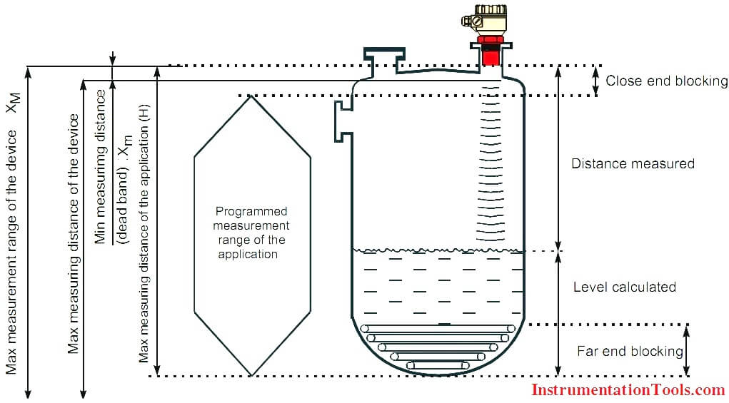
Basic Concept and Elements of the Ultrasonic Level Measurement
Minimum measuring distance (Xm): (also known as the “Dead Band”) is a feature common to all ultrasonic level meters. This is a short range in front of the sensor within which the ultrasonic device can not measure.
Maximum measuring distance (XM): The longest range under ideal condition within which the device can measure. No measurement is possible beyond this distance.
Ultrasonic level transmitter, which performs calculations to convert the distance of wave travel into a measure of level in the tank. The time lapse between firing the sound burst and receiving the return echo is directly proportional to the distance between the transducer and the material in the vessel. The medium is normally air over the material’s surface but it could be a blanket of some other gases or vapours. The instrument measures the time for the bursts to travel down to the reflecting surface and return. This time will be proportional to the distance from the transducer to the surface and can be used to determine the level of fluid in the tank. This basic principle lies at the heart of the ultrasonic measurement technology and is illustrated in the equation: Distance = (Velocity of Sound x Time)/2. These noncontact devices are available in models that can convert readings into 4–20 mA outputs to DCSs, PLCs, or other remote systems.
The frequency range for ultrasonic methods is in the range of 15…200 kHz. The lower frequency instruments are used for more difficult applications; such as longer distances and solid level measurements and those with higher frequency are used for shorter liquid level measurements.
For practical applications of ultrasonic measurement method, a number of factors must be considered. A few key points are:
- The speed of sound through the medium (usually air) varies with the medium’s temperature. The transducer may contain a temperature sensor to compensate for changes in operating temperature that would alter the speed of sound and hence the distance calculation that determines an accurate level measurement. Temperature compensation is provided to account for uniform temperature variances of the sound medium. The temperature sensor is placed inside the transducer and the signal is sent to the transceiver via the transducer’s wiring. Optionally, an alternate temperature sensor can be used to provide a temperature input, rather than by using the integral temperature sensor. If the temperature of the sound medium is to remain constant, instead of using either the integral temperature compensation or the remote sensor, the desired temperature may be entered during the transceiver configuration.
- The presence of heavy foam/dust on the surface of the material can act as a sound absorbent. In some cases, the absorption may be sufficient to preclude use of the ultrasonic technique. To enhance performance where foam/dust or other factors affect the wave travel to and from the liquid surface, some models can have a beam guide attached to the transducer.
- Extreme turbulence of the liquid can cause fluctuating readings. Use of a damping adjustment in the instrument or a response delay may help overcome this problem. The transceiver provides damping to control the maximum changing rate of the displayed material level and fluctuation of the mA output signal. Damping slows down the rate of response of the display especially when liquid surfaces are in agitation or material falls into the sound path during filling.
Advantages
- Ultrasonic transmitters are easy to install on empty tanks or on tanks containing liquid.
- Set-up is simple and those devices with on-board programming capability can be configured in minutes.
- As there is no contact with the media and no moving parts, the devices are virtually maintenance free. Wetted materials are usually an inert fluoropolymer, and resistant to corrosion from condensing vapors.
- Because the device is non-contacting, the level measurement is unaffected by changes in the liquid density, dielectric, or viscosity, and performs well on aqueous liquids and many chemicals.
- Changes in process temperature will change the speed of the ultrasonic pulse through the space above the liquid, but built-in temperature compensation automatically corrects this.
- Changes in process pressure do not affect the measurement.
Limitations
- Ultrasonic transmitters rely on the pulse being unaffected during its flight time. Liquids which form heavy vapors, steam or vapor layers should be avoided (use a Radar transmitter in these instances). As the pulse needs air to travel through, vacuum applications are not possible.
- Materials of construction generally limit the process temperature to around 158 °F (70 °C) and pressure to 43 psig (3 bar).
- The condition of the liquid surface is also important. Some turbulence can be tolerated but foaming will often damp out the return echo.
- Obstructions in the tank, such as pipes, strengthening bars and agitators, will cause false echoes, but most transmitters have sophisticated software algorithms to allow masking or ignoring of these echoes.
- Ultrasonic transmitters can be used on silos containing dry products such as pellets, grains or powders, but these are more difficult to commission. Factors such as surface angle of repose, dusting and long ranges must be taken into account. A Guided Wave Radar transmitter is better suited to dry product applications.


thank you for this valuable information..
sir.. thank you so much for your information. But i have a question. Can the ultrasonic sensor be used in sand? for the level measurement. Whatever the answer is can i know why? i really need to know it sir. Please help.
hey may i know why does it the distance calculation divided by 2? is it because it relates to the distance of transmission and distance of reception?
Yes, because the pulse generated by the transmitter travels 2 times the distance: from transmitter to the liquid surface and back.
Thank you, your article is very informative.
May i know what is the unit of the distance or can you give the sample question on how to calculate it