Inst ToolsInst ToolsInst Tools
  • Courses
  • Automation
    • PLC
    • Control System
    • Safety System
    • Communication
    • Fire & Gas System
  • Instrumentation
    • Design
    • Pressure
    • Temperature
    • Flow
    • Level
    • Vibration
    • Analyzer
    • Control Valve
    • Switch
    • Calibration
    • Erection & Commissioning
  • Interview
    • Instrumentation
    • Electrical
    • Electronics
    • Practical
  • Q&A
    • Instrumentation
    • Control System
    • Electrical
    • Electronics
    • Analog Electronics
    • Digital Electronics
    • Power Electronics
    • Microprocessor
Search
  • Books
  • Software
  • Projects
  • Process
  • Tools
  • Basics
  • Formula
  • Power Plant
  • Root Cause Analysis
  • Electrical Basics
  • Animation
  • Standards
  • 4-20 mA Course
  • Siemens PLC Course
Reading: Ultrasonic Level Transmitter Animation
Share
Notification Show More
Font ResizerAa
Inst ToolsInst Tools
Font ResizerAa
  • Courses
  • PLC
  • Control Systems
Search
  • Courses
  • Automation
    • PLC
    • Control System
    • Safety System
    • Communication
    • Fire & Gas System
  • Instrumentation
    • Design
    • Pressure
    • Temperature
    • Flow
    • Level
    • Vibration
    • Analyzer
    • Control Valve
    • Switch
    • Calibration
    • Erection & Commissioning
  • Interview
    • Instrumentation
    • Electrical
    • Electronics
    • Practical
  • Q&A
    • Instrumentation
    • Control System
    • Electrical
    • Electronics
    • Analog Electronics
    • Digital Electronics
    • Power Electronics
    • Microprocessor
Follow US
All rights reserved. Reproduction in whole or in part without written permission is prohibited.
Inst Tools > Blog > Animation > Ultrasonic Level Transmitter Animation

Ultrasonic Level Transmitter Animation

Last updated: September 14, 2016 6:42 pm
Editorial Staff
Animation How It Works Level Measurement
6 Comments
Share
0 Min Read
SHARE
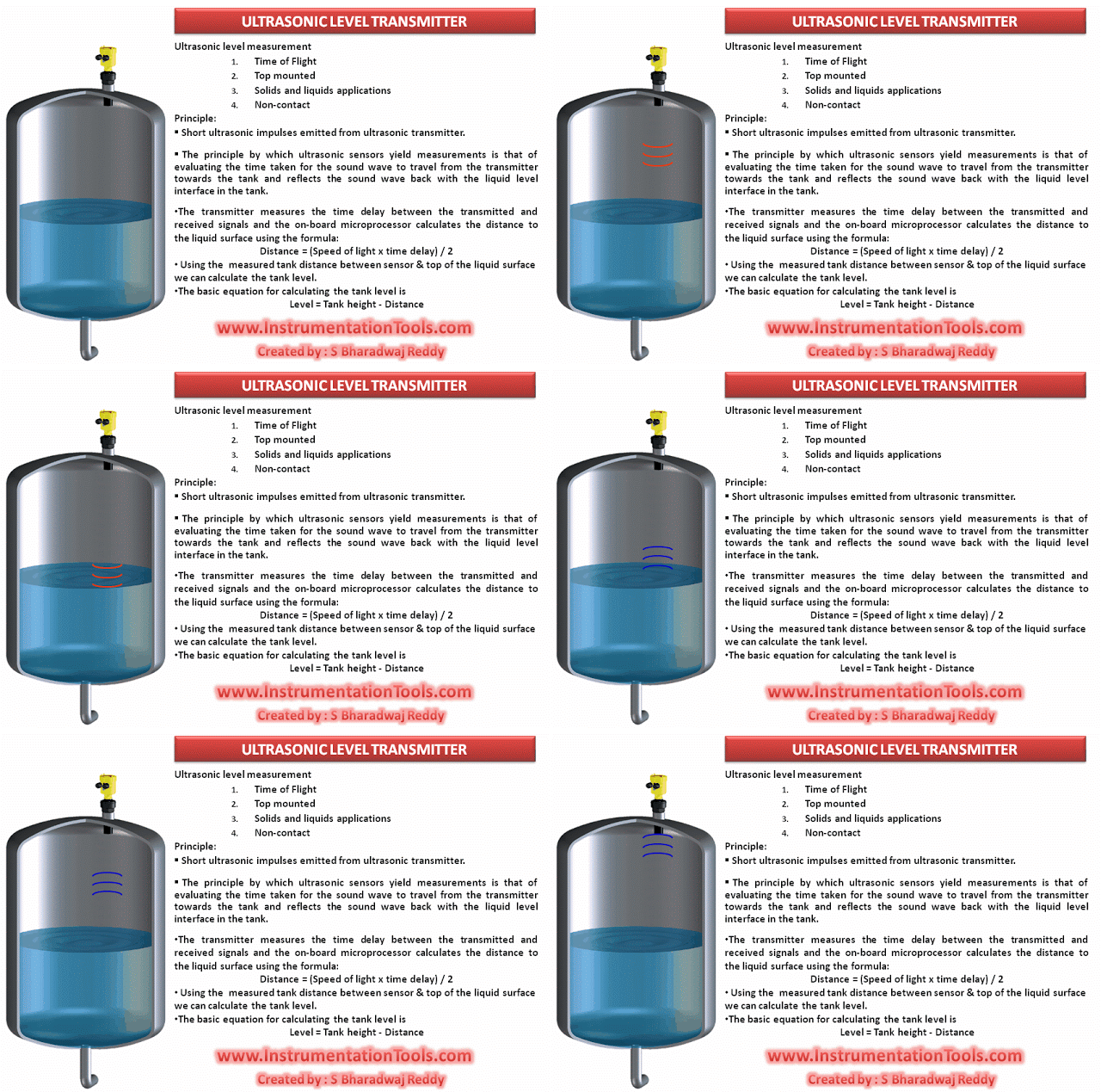
Ultrasonic Level Transmitter Animation

Ultrasonic Level Transmitter Animation shows the working principle of ultrasonic level sensors visually.

Also See :  Ultrasonic Level Transmitter Working Principle


Don't Miss Our Updates
Be the first to get exclusive content straight to your email.
We promise not to spam you. You can unsubscribe at any time.
Invalid email address
You've successfully subscribed !

Continue Reading

Coriolis Mass Flow Meter Working Principle
Digital Building Blocks – GATES
Non Contacting Radar Level Transmitter Animation
Microwave Flow Sensor – Working Principle and Applications
4-20mA Junction Box versus Fieldbus (FF) Junction Box
Basics of Globe Valves
Share This Article
Facebook Whatsapp Whatsapp LinkedIn Copy Link
Share
6 Comments
  • Santhosh Kumar says:
    June 4, 2015 at 6:54 pm

    Lovely…Good Animation.

    Reply
  • ruptus gog says:
    September 7, 2015 at 8:37 pm

    WONDERFUL Post.thanks for share..more wait .. …

    Reply
  • Barrett Mena says:
    October 11, 2015 at 7:51 am

    Thanks for sharing your knowledge.

    Reply
  • Keeter says:
    October 17, 2015 at 8:46 am

    This is one awesome post.Really thank you!

    Reply
  • Justin James says:
    July 23, 2019 at 6:31 pm

    An ultrasonic transmitter is being used to measure liquid level in a process vessel. The liquid level in the vessel is 2.8 m. If the transit time of the ultrasonic signal from the sensor to the liquid surface and its return is 8.3 ms, calculate the distance from the sensor to the bottom of the vessel. The velocity of sound through the medium is 342 m/s.

    what will be the answer, which equation needs to be used?

    Reply
  • Ibrahim khleifat says:
    December 21, 2019 at 5:57 pm

    Distance = speed of sound x Td/2 = 342 m/s x 8.3 ms / 2 = 342 m/s x 8.3 x0.001/2 = 342 m/s x0.00415 = 1.42 m

    Tank height = liquid level + distance = 2.8m + 1.42 m = 4.22 m

    Reply

Leave a Reply Cancel reply

Your email address will not be published. Required fields are marked *

Stay Connected

128.3kFollowersLike
69.1kFollowersFollow
208kSubscribersSubscribe
38kFollowersFollow

Categories

Explore More

PLC Sinking and Sourcing Explanation
Capacitance Level Sensor Principle, Limitations, Installation & Calibration
DP Level Transmitters Compensation Techniques
Displacer Interface Level Measurement
Oval Gear Flow Meters – Principle, Advantages, Animation
Nutating Disc Flow Meters Working Principle
Pushbutton switches and Types of Switches
Paddle Wheel Level Switch Principle

Keep Learning

Torque Tube Level Measurement Principle

Torque Tube Level Measurement Principle

Venturi Flow Meter

Venturi Flow Meter – Working Principle, Advantages, Animation

Reflex Level Gauge Parts

What is Reflex Level Gauge?

Differential Pressure Level Transmitter Errors

Differential Pressure Level Transmitter Errors

Swirl Flowmeters Principle

Swirl Flow Meters Working Principle

Control Valve Working Animation

Control Valve Working Animation

remote seal capillary type dp transmitter

Closed Tank Remote Seal Capillary type DP Transmitter

Deluge Valve Operation

Deluge Valve Working Principle

Learn More

FPGA vs. CPLD - What are the differences between them

FPGA vs. CPLD – What are the differences between them

250+ Control System MCQ

250+ Control System MCQ Test Questions

Control Valve End Connection

Control Valve End Connection

Feedback Control Questions & Answers

Feedback Control Loop Questions & Answers

PLC Program for Fishpond Water Level Monitoring System

PLC Program for Artificial Fishpond Water Level Monitoring System

Analog signal with noise

Signal Coupling and Cable Separation

Baffle Nozzle Question

Baffle Nozzle Question

Flow Meter Questions and Answers

Flow Meter Questions and Answers

Follow US
All rights reserved. Reproduction in whole or in part without written permission is prohibited.
Welcome Back!

Sign in to your account

Username or Email Address
Password

Lost your password?