There are two general methods of cathodic protection,
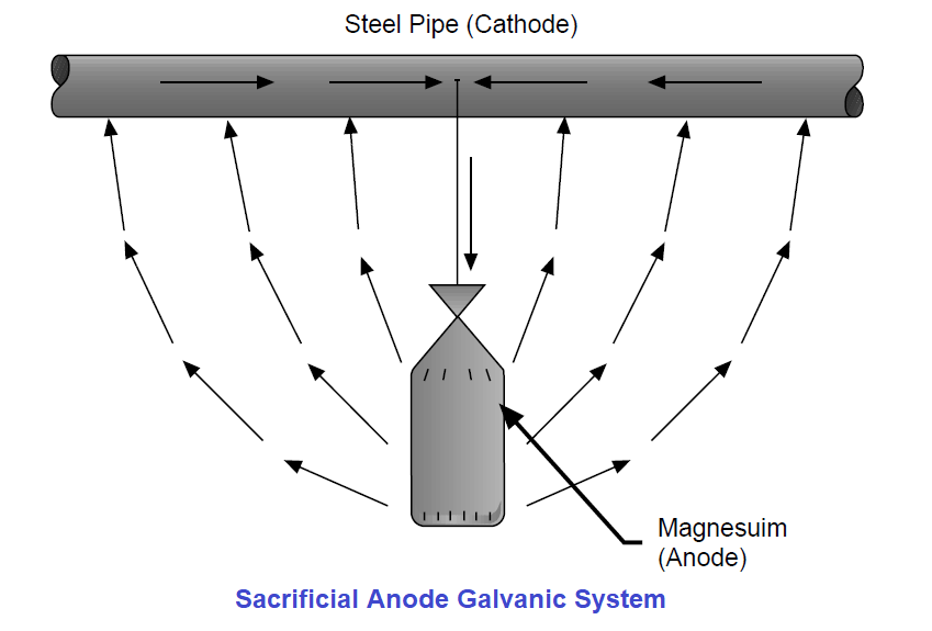
The galvanic system uses a sacrificial anode of a material having a higher potential on the electromotive series than the material to be protected (Fig. 1).

Fig: 1
Magnesium, zinc or aluminum are typical sacrificial anode materials. These anodes are designed to corrode and “sacrifice” themselves to protect the pipe, tank, etc. The anodes must be large enough to provide protection for a reasonable length of time before they are dissipated. Then they must be replaced for protection to continue.
The electromotive series (Table 1) lists several materials from the most anodic, or most active, at the top of the list to the most cathodic, or least active, at the bottom of the list. Also listed is the voltage or potential of the materials in seawater in relation to hydrogen. Any material on the list will protect any material listed below it.
Table: 1
The impressed current system uses an outside source of electricity from a DC power supply, powered by solar, wind or the power company. This system uses a DC current of a magnitude greater than, and flowing in the opposite direction to, the natural galvanic cell current.
An anode is also required with the impressed current system but it can be of an inexpensive material such as scrap steel or graphite (Fig. 2). There is practically no limit on the current output in an impressed current system.
Fig: 2
To conserve the current requirements for cathodic protection on a pipeline, normal installation practice calls for pipes to be coated to insulate the pipe from the corrosive environment. However, these coatings are never perfect and/or are damaged when the pipe is installed. The breaks in the coating (called holidays) are protected by the cathodic protection system. Since the amount of steel exposed at the holidays is very small compared to a bare pipeline, the amount of current required to protect the pipeline is reduced in a direct ratio.
To protect the pipeline in the case of stray current, the pipe must be bonded to the negative side of the DC power supply station with a low resistance conductor. This provides a direct metallic path for the return current to follow as it leaves the pipe (Fig. 3).
Fig: 3
1. Bonding together of all structures (tanks, pipes, both across joints and between different pipes, etc.) is of absolute necessity for proper protection. This will provide a metallic return current path for any cathodic current.
2. A study is needed to determine any effect of the cathodic protection system on any “foreign” (owned by others) nearby structures. Any cathodic protection current picked up by a foreign structure must also leave that structure – which may cause corrosion.
Let us look at the electrical connections required in a cathodic protection system and why they are different than those required for a grounding system.
Cathodic connections are low current connections rather than grounding connections. Grounding connections are required to withstand damage while conducting huge surges of ground fault current. Cathodic protection connections are required to carry only a small but continuous current. Therefore cathodic protection connections do not have to be as massive as grounding connections.
A very low resistance system is required for a cathodic protection system, and it must remain low in resistance over the life of the system. The higher the resistance, the less efficient is the cathodic protection system. Cathodic Protection Connections meet this low resistance requirement, both when installed and over the life of the system.
The pipe used in transmission pipeline systems is usually a highly stressed thin wall steel pipe. Any connection to this pipe by the cathodic protection wires or the test leads must not damage the pipe. Cathodic Protection Connections use a special alloy weld metal developed to minimize the effect the weld has on the pipe. These connections have been proven by independent tests not to be detrimental to the pipe, and more than 45 years of usage without any detrimental effects have provided field proof to the tests.
Do you face any problems with cathodic protection? Share with us.
Reference: erico
PLC ladder logic design to control 3 motors with toggle switch and explain the program…
VFD simulator download: Master the online tool from the Yaskawa V1000 & programming software for…
The conveyor sorting machine is widely used in the packing industries using the PLC program…
Learn the example of flip-flop PLC program for lamps application using the ladder logic to…
In this article, you will learn the STAR DELTA programming using PLC controller to start…
Lube oil consoles of rotary equipment packages in industrial process plants are usually equipped with…
View Comments
Good to see these helpful information here,Thanks lots for sharing them with us.