Inst ToolsInst ToolsInst Tools
  • Courses
  • Automation
    • PLC
    • Control System
    • Safety System
    • Communication
    • Fire & Gas System
  • Instrumentation
    • Design
    • Pressure
    • Temperature
    • Flow
    • Level
    • Vibration
    • Analyzer
    • Control Valve
    • Switch
    • Calibration
    • Erection & Commissioning
  • Interview
    • Instrumentation
    • Electrical
    • Electronics
    • Practical
  • Q&A
    • Instrumentation
    • Control System
    • Electrical
    • Electronics
    • Analog Electronics
    • Digital Electronics
    • Power Electronics
    • Microprocessor
  • Request
Search
  • Books
  • Software
  • Projects
  • Process
  • Tools
  • Basics
  • Formula
  • Power Plant
  • Root Cause Analysis
  • Electrical Basics
  • Animation
  • Standards
  • 4-20 mA Course
  • Siemens PLC Course
Reading: Turbidity Sensor Calibration Procedure
Share
Font ResizerAa
Inst ToolsInst Tools
Font ResizerAa
  • Courses
  • Design
  • PLC
  • Interview
  • Control System
Search
  • Courses
  • Automation
    • PLC
    • Control System
    • Safety System
    • Communication
    • Fire & Gas System
  • Instrumentation
    • Design
    • Pressure
    • Temperature
    • Flow
    • Level
    • Vibration
    • Analyzer
    • Control Valve
    • Switch
    • Calibration
    • Erection & Commissioning
  • Interview
    • Instrumentation
    • Electrical
    • Electronics
    • Practical
  • Q&A
    • Instrumentation
    • Control System
    • Electrical
    • Electronics
    • Analog Electronics
    • Digital Electronics
    • Power Electronics
    • Microprocessor
  • Request
Follow US
All rights reserved. Reproduction in whole or in part without written permission is prohibited.
Inst Tools > Blog > Analyzers > Turbidity Sensor Calibration Procedure

Turbidity Sensor Calibration Procedure

Last updated: September 14, 2016 10:56 pm
Editorial Staff
Analyzers Calibration
No Comments
Share
3 Min Read
SHARE

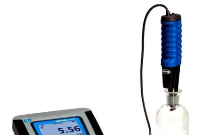
The turbidity method is based upon a comparison of intensity of light scattered by a sample under defined conditions with the intensity of light scattered by a standard reference suspension. A turbidimeter is a nephelometer with a visible light source for illuminating the sample and one or more photo-electric detectors placed ninety degrees to the path of the light source. Note: the below calibration procedure is for a turbidimeter which the sample is placed into a cuvette.

Some instruments will only accept one standard. For those instruments, the second, third, etc., standards will serve as check points.

Calibration Procedure:

1. Allow the calibration standards to equilibrate at the ambient temperature. The use of commercially available polymer primary standards (AMCO-AEPA-l) is preferred; however, the standards can be prepared using Formazin (read the warning on the label before use) according to the EPA analytical Method 180.1. Other standards may be used if they can be shown that they are equivalent to the previously mentioned standards.

2. If the standard cuvette is not sealed, rinse a cuvette with deionized water. Shake the cuvette to remove as much water as possible. Do not wipe dry the inside of the cuvette because lint from the wipe may remain in the cuvette. Add the standard to the cuvette.

3. Before performing the calibration procedure, make sure the cuvettes are not scratched and the outside surfaces are dry and free from fingerprints and dust. If the cuvette is scratched or dirty, discard or clean the cuvette respectively. Note: some . manufacturers require the cuvette to be orientated in the instrument in a particular direction for accurate reading.

4. Select a low value standard such as a zero or 0.02 NTU and calibrate according to manufacturer’s instructions. Note: a zero standard (approximately 0 NTU) can be prepared by passing distilled water through a 0.45 micron pore size membrane filter.

5. Select a high standard and calibrate according to manufacturer’s instructions or verify the calibration if instrument will not accept a second standard. In verifying, the instrument should read the standard value to within the specifications of the instrument. If the instrument has range of scales, check each range that will be used during the sampling event with a standard that falls within that range.

6. Record the calibration information on calibration log sheet.

Don't Miss Our Updates
Be the first to get exclusive content straight to your email.
We promise not to spam you. You can unsubscribe at any time.
Invalid email address
You've successfully subscribed !

Continue Reading

Calibration of Measuring Instruments – Significance, Costs & Risks
Stroke Checking Procedure for GCV, SRV, IGV, and LFBV
Impulse Line Pressure Testing Procedure
Displacer (buoyancy) Level Transmitter Principle, Limitations, Design, Installation & Calibration
Calibration and Troubleshooting of Oxygen Analyzer
Ammonia Gas Detector Working Principle and Calibration
Share This Article
Facebook Whatsapp Whatsapp LinkedIn Copy Link
Share
Leave a Comment

Leave a Reply Cancel reply

Your email address will not be published. Required fields are marked *

Stay Connected

128.3kFollowersLike
69.1kFollowersFollow
210kSubscribersSubscribe
38kFollowersFollow

Categories

Explore More

Ultrasonic Level Transmitter Principle, Limitations, Calibration and configuration
How to Calibrate Load Cells in Weighing Applications?
Difference between Accuracy, Tolerance, Uncertainty, and Error
Differential Pressure Sensors Calibration Procedure
Pulsed Fluorescence SO2, H2S, CS Analyzer Working Principle
Important Terms in Calibration
Uncertainty Calculations of Pressure Calibration
Calibration : Up-tests and Down-tests

Keep Learning

RTD Testing Methods

RTD Testing Methods in Calibration Laboratory

Flow Meter Calibration Procedure

Flow Meter Calibration

SWAS Analyzer Questions

SWAS Analyzers Questions and Answers

Pressure Gauge Calibration according to Standard DKD-R-6-1

Pressure Gauge Calibration according to Standard DKD-R-6-1

pH Analyzer Do’s and Don’ts

pH Analyzer Do’s and Don’ts

H2 S and Total Sulfur Using Lead Acetate Principle

H2S Measurement Using Lead Acetate Principle

Temperature Switch Calibration

How to Calibrate Temperature Switch? – Instrument Basics

Vibration Probe Field Setting Procedure

How to do calibration checks of vibration Probe, extension cable and vibration monitor

Learn More

Grounding or Earthing Scheme in DCS or PLC Systems

Grounding or Earthing Scheme in DCS or PLC Systems

PLC analog input scaling

PLC Analog Input Scaling

Instrumentation Functional Diagrams Principle

Instrumentation Functional diagrams

Digital Electronics Multiple Choice Questions

Flip Flops Objective Questions – Part 3

Safety PLC Programming steps

Safety Door Interlock PLC Program

Instrumentation Engineer’s Calibration Mistakes

Control Valve Direction of Control Action

PID Controller Action : Directing Acting & Reverse Acting

Calibrating Transmitter System One Seal with suppressed Zero

Calibrating Level Transmitter with Remote Seals

Menu

  • About
  • Privacy Policy
  • Copyright

Quick Links

  • Learn PLC
  • Helping Hand
  • Part Time Job

YouTube Subscribe

Follow US
All rights reserved. Reproduction in whole or in part without written permission is prohibited.
Welcome Back!

Sign in to your account

Username or Email Address
Password

Lost your password?