Inst ToolsInst ToolsInst Tools
  • Courses
  • Automation
    • PLC
    • Control System
    • Safety System
    • Communication
    • Fire & Gas System
  • Instrumentation
    • Design
    • Pressure
    • Temperature
    • Flow
    • Level
    • Vibration
    • Analyzer
    • Control Valve
    • Switch
    • Calibration
    • Erection & Commissioning
  • Interview
    • Instrumentation
    • Electrical
    • Electronics
    • Practical
  • Q&A
    • Instrumentation
    • Control System
    • Electrical
    • Electronics
    • Analog Electronics
    • Digital Electronics
    • Power Electronics
    • Microprocessor
  • Request
Search
  • Books
  • Software
  • Projects
  • Process
  • Tools
  • Basics
  • Formula
  • Power Plant
  • Root Cause Analysis
  • Electrical Basics
  • Animation
  • Standards
  • 4-20 mA Course
  • Siemens PLC Course
Reading: Turbidity Analyzer Working Principle
Share
Font ResizerAa
Inst ToolsInst Tools
Font ResizerAa
  • Courses
  • Design
  • PLC
  • Interview
  • Control System
Search
  • Courses
  • Automation
    • PLC
    • Control System
    • Safety System
    • Communication
    • Fire & Gas System
  • Instrumentation
    • Design
    • Pressure
    • Temperature
    • Flow
    • Level
    • Vibration
    • Analyzer
    • Control Valve
    • Switch
    • Calibration
    • Erection & Commissioning
  • Interview
    • Instrumentation
    • Electrical
    • Electronics
    • Practical
  • Q&A
    • Instrumentation
    • Control System
    • Electrical
    • Electronics
    • Analog Electronics
    • Digital Electronics
    • Power Electronics
    • Microprocessor
  • Request
Follow US
All rights reserved. Reproduction in whole or in part without written permission is prohibited.
Inst Tools > Blog > Analyzers > Turbidity Analyzer Working Principle

Turbidity Analyzer Working Principle

Last updated: May 8, 2017 5:06 pm
Editorial Staff
Analyzers
No Comments
Share
3 Min Read
SHARE

Turbidity is an optical property of water based on the amount of light scattered and absorped by collodial and suspended particles. The turbidity value measured in FNU, FTU, NTU etc. is the quantitative statement of this qualitative phenomenon.

Nephelometry means that the light source and the photodetector are set at a 90-degree angle from each other. This is considered the angle most sensitive to light scatter regardless of particle size

Nephelometry Turbidity Analzer Principle

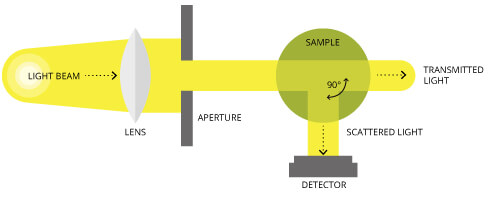
The goal of measuring turbidity is to get an indication for the concentration of scattering particles in a medium. This can be done by determination of the light loss of the transmitted beam or the measurement of the light scattered sideways. Both methods deliver proportional data to particle concentration and are therefore suitable for measuring turbidity. They however differ in application and concentration levels. Scattered light measurement principle is more suitable for the detection of lower concentrations, while transmission (reflection or absorption) measurement is used for higher concentrations.

Turbidity Analyzer Working Principle

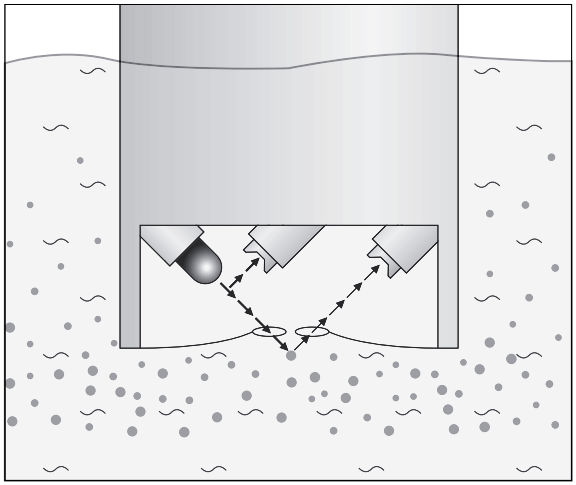
Image Credits : krohne

The device measures scatted light at 90° which is according to ISO 7027 / DIN EN 27027 to be used for turbidity values below 40 NTU.The NIR light source and receiver are positioned in a 90° angle to each other. The light transmitted from the source is directed in equal strength to the reference detector and into the medium. Light is scattered from the particles and the portion which is scattered at a 90° angle is received by the detector. The meter now compares the light from the reference detector and scattered light receiver and calculates the turbidity value.

The measurement unit for the turbidity measured at a 90° angle varies depending on country in and is according to ISO 7027 Formazine Nephelometric Unit (FNU), but the more commonly used terminology is Nephelometric Turbidity Unit (NTU) stated within the US EPA 180.1. Both units compare 1 to 1.

The advantage of the using NIR as light source as stated in the ISO 7027 is that this sensor is not affected by colour of the medium measured.

Source : krohne

Don't Miss Our Updates
Be the first to get exclusive content straight to your email.
We promise not to spam you. You can unsubscribe at any time.
Invalid email address
You've successfully subscribed !

Continue Reading

What is Infrared Flue Gas Analyzer? – Working Principle
Total Organic Carbon Analyzers Questions and Answers
Chemiluminescence
pH measurement
pH Analyzer Interview Questions and Answers
What is Gas Metering System?
Share This Article
Facebook Whatsapp Whatsapp LinkedIn Copy Link
Share
Leave a Comment

Leave a Reply Cancel reply

Your email address will not be published. Required fields are marked *

Stay Connected

128.3kFollowersLike
69.1kFollowersFollow
210kSubscribersSubscribe
38kFollowersFollow

Categories

Explore More

Fluorescence
Sling Psychrometer Principle
Oxidation-Reduction Potential (ORP) Sensor Calibration Procedure
Oxygen Analyzer Working Principle
SWAS Analyzers Questions and Answers
Ammonia Analyzer Principle
Humidity Measurement Principle
Ammonia Gas Detector Working Principle and Calibration

Keep Learning

Calibration and Troubleshooting of Oxygen Analyzer

Calibration and Troubleshooting of Oxygen Analyzer

Moisture and Dew Point Analyzer Problems

Moisture and Dew Point Analyzer Problems and Troubleshooting Tips

toroidal conductivity probe principle

Conductivity Analyzer Common Problems and Troubleshooting Tips

Gas Analyzers Interview Questions

Gas Analyzers Interview Questions and Answers

Analyzer chopper wheel

NDIR Analyzer Filter Cells

Various Types of Sensors Used in Water Treatment Plant

Various Types of Sensors used in Water Treatment Plant

Luft detector

Luft detector Principle

Conductivity measurement

Conductivity Measurement

Learn More

Digital Electronics Multiple Choice Questions

4-Bit Parallel Adder and Subtractor Objective Questions

Applications of Photo diodes

Applications of Photo diodes

Flowmeter Characteristics

Flow Meter Characteristics

PLC Motor Control Circuit

Motor Trip Logic using PLC Programming

foundation-fieldbus-vs-profibus

Comparison between Foundation Fieldbus and Profibus

hydrostatic interface measurement calculation

Hydrostatic Pressure Measurement Questions

Electronics Projects

500 Electronics Projects for Engineering Students

Difference between KW and KVA

Difference between KW and KVA

Menu

  • About
  • Privacy Policy
  • Copyright

Quick Links

  • Learn PLC
  • Helping Hand
  • Part Time Job

YouTube Subscribe

Follow US
All rights reserved. Reproduction in whole or in part without written permission is prohibited.
Welcome Back!

Sign in to your account

Username or Email Address
Password

Lost your password?