Sometimes ammeter or current measurement with multimeter is unavailable at work locations , we can still perform useful troubleshooting measurements using nothing but a DC voltmeter / Multimeter with DC voltage measurement.
Here, however, one must be careful of how to interpret these voltage measurements, for they may not directly correspond to the loop current as was the case with measurements taken in parallel with the precision resistor.
Take for example this 4-20 mA loop where a controller sends a command signal to an I/P transducer:
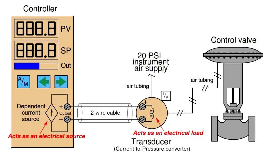
There is no standardized resistance value for I/P transducer coils, and so the amount of voltage dropped across the I/P terminals for any given amount of loop current will be unique for every different model of I/P.
The Fisher model 567 I/P transducer built for 4-20 mA signals has a normal coil resistance of 176 ohms.
Thus, we would expect to see a voltage drop of approximately 0.7 volts at 4 mA and a drop of approximately 3.5 volts at 20 mA across the I/P terminals.
Since the controller output terminals are directly in parallel with the I/P terminals, we would expect to see approximately the same voltage there as well (slightly greater due to wire resistance).
The lack of known precision in the I/P coil resistance makes it difficult to tell exactly how much current is in the loop for any given voltage measurement we take with a voltmeter.
However, if we do know the approximate coil resistance of the I/P, we can at least obtain an estimate of loop current, which is usually good enough for diagnostic purposes.
If the I/P coil resistance is completely unknown, voltage measurements become useless for quantitative determination of loop current.
Voltage measurements would be useful only for qualitatively determining loop continuity (i.e. whether there is a break in the wiring between the controller and I/P).
Another example for consideration is this loop-powered 4-20 mA transmitter and controller circuit, where the controller supplies DC power for the loop:
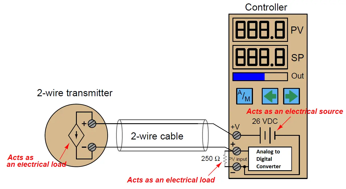
It is very common to find controllers with their own built-in loop power supplies, due to the popularity of loop-powered (2-wire) 4-20 mA transmitters.
If we know the transmitter requires a DC voltage source somewhere in the circuit to power it up, it makes sense to include one in the controller, right?
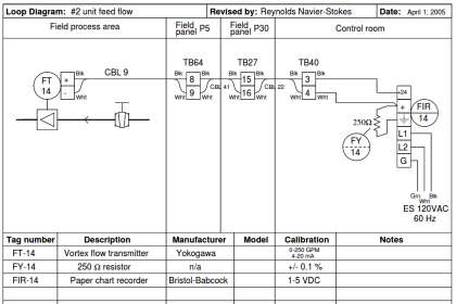
The only voltage measurement that directly and accurately corresponds to loop current is the voltage directly across the 250 ohm precision resistor.
A loop current of 4 mA will yield a voltage drop of 1 volt, 12 mA will drop 3 volts, 20 mA will drop 5 volts, etc.
A voltage measurement across the transmitter terminals will show us the difference in voltage between the 26 volt power supply and the voltage dropped across the 250 ohm resistor.
In other words, the transmitter’s terminal voltage is simply what is left over from the source voltage of 26 volts after subtracting the resistor’s voltage drop.
This makes the transmitter terminal voltage inversely proportional to loop current: the transmitter sees approximately 25 volts at 4 mA loop current (0% signal) and approximately 21 volts at 20 mA loop current (100% signal).
The use of the word “approximate” is very intentional here, for loop power supplies are usually non-regulated. In other words, the “26 volt” rating is approximate and subject to change!
One of the advantages of the loop-powered transmitter circuit is that the source voltage is largely irrelevant, so long as it exceeds the minimum value necessary to ensure adequate power to the transmitter.
If the source voltage drifts for any reason, it will have no impact on the measurement signal at all, because the transmitter is built as a current regulator, regulating current in the loop to whatever value represents the process measurement, regardless of slight changes in loop source voltage, wire resistance, etc.
This rejection of power supply voltage changes means the loop power supply need not be regulated, and so in practice it rarely is.
This brings us to a common problem in loop-powered 4-20 mA transmitter circuits: maintaining sufficient operating voltage at the transmitter terminals.
Recall that a loop-powered transmitter relies on the voltage dropped across its terminals (combined with a current of less than 4 mA) to power its internal workings.
This means the terminal voltage must not be allowed to dip below a certain minimum value, or else the transmitter will not have enough electrical power to continue its normal operation.
This makes it possible to “starve” the transmitter of voltage if the loop power supply voltage is insufficient, and/or if the loop resistance is excessive.
To illustrate how this can be a problem, consider the following 4-20 mA measurement loop, where the controller supplies only 20 volts DC to power the loop, and an indicator is included in the circuit to provide operators with a field-mounted indication of the transmitter’s measurement:
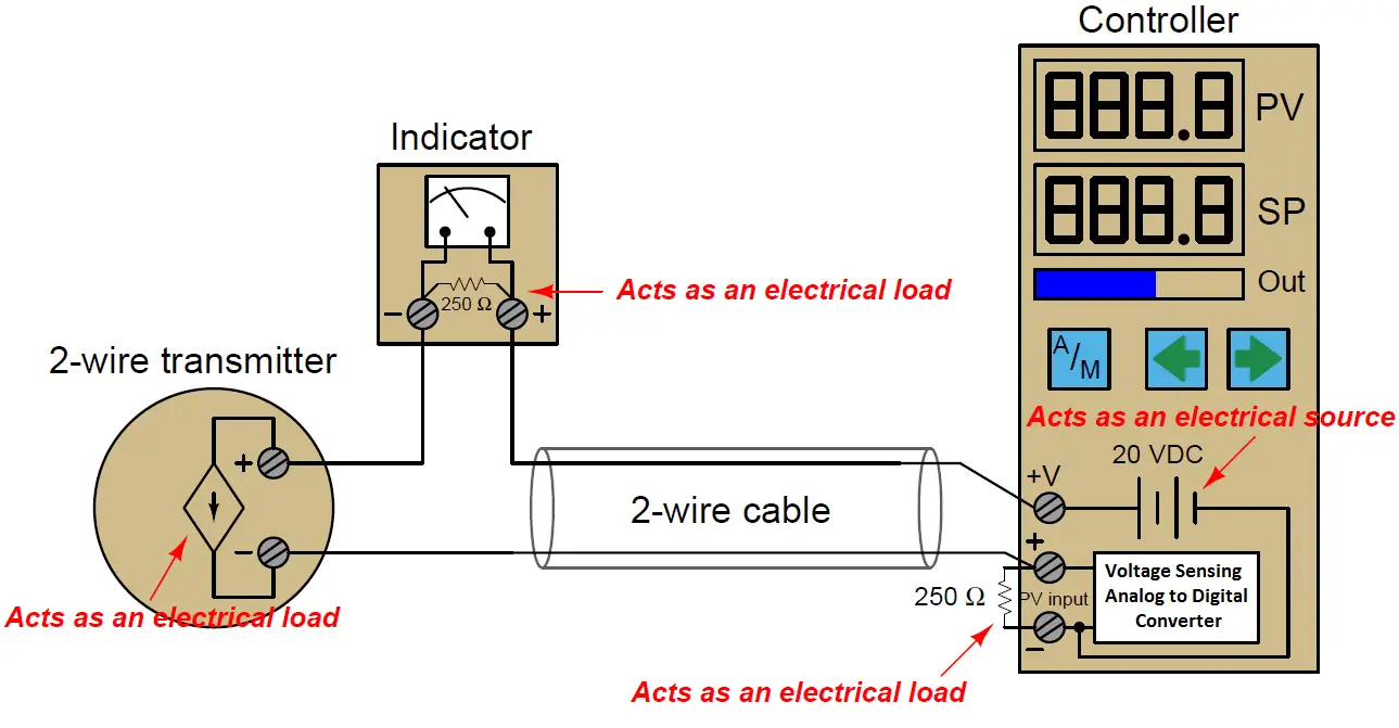
The indicator contains its own 250 ohm resistor to provide a 1-5 volt signal for the meter mechanism to sense. This means the total loop resistance has now risen from 250 ohms to 500 ohms (plus any wire resistance).
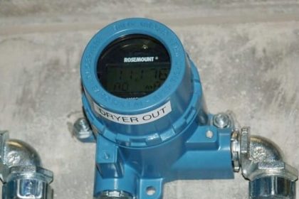
At full current (20 mA), this total circuit resistance will drop (at least) 10 volts, leaving 10 volts or less at the transmitter terminals to power the transmitter’s internal workings. 10 volts may not be enough for the transmitter to successfully operate, though. The Rosemount model 3051 pressure transmitter, for example, requires a minimum of 10.5 volts at the terminals to operate.
However, the transmitter will operate just fine at lower loop current levels. When the loop current is only 4 mA, for example, the combined voltage drop across the two 250 ohm resistors will be only 2 volts, leaving about 18 volts at the transmitter terminals: more than enough for practically any model of 4-20 mA loop-powered transmitter to successfully operate.
Thus, the problem of insufficient supply voltage only manifests itself when the process measurement nears 100% of range.
This could be a difficult problem to diagnose, since it appears only during certain process conditions and not others. A technician looking only for wiring faults (loose connections, corroded terminals, etc.) would never find the problem.
When a loop-powered transmitter is starved of voltage, its behavior becomes erratic. This is especially true of “smart” transmitters with built-in microprocessor circuitry. If the terminal voltage dips below the required minimum, the microprocessor circuit shuts down. When the circuit shuts down, the current draw decreases accordingly.
This causes the terminal voltage to rise again, at which point the microprocessor has enough voltage to start up.
As the microprocessor “boots” back up again, it increases loop current to reflect the near-100% process measurement. This causes the terminal voltage to sag, which subsequently causes the microprocessor to shut down again.
The result is a slow on/off cycling of the transmitter’s current, which makes the process controller think the process variable is surging wildly.
The problem disappears, though, as soon as the process measurement decreases enough that the transmitter is allowed enough terminal voltage to operate normally.
Credits : by Tony R. Kuphaldt – Creative Commons Attribution 4.0 License


Hi
What is minimum mAmp you should measure before there is a fault. Can you read below 4 mAmps ? Would the sensor be faulty if you read 2 Amp etc etc ??
Recently a PLC was in alarm reading 0 mAmp from Hydrostatic sensor in a sewer pit.
Thank you for great articles