Inst ToolsInst ToolsInst Tools
  • Courses
  • Automation
    • PLC
    • Control System
    • Safety System
    • Communication
    • Fire & Gas System
  • Instrumentation
    • Design
    • Pressure
    • Temperature
    • Flow
    • Level
    • Vibration
    • Analyzer
    • Control Valve
    • Switch
    • Calibration
    • Erection & Commissioning
  • Interview
    • Instrumentation
    • Electrical
    • Electronics
    • Practical
  • Q&A
    • Instrumentation
    • Control System
    • Electrical
    • Electronics
    • Analog Electronics
    • Digital Electronics
    • Power Electronics
    • Microprocessor
  • Request
Search
  • Books
  • Software
  • Projects
  • Process
  • Tools
  • Basics
  • Formula
  • Power Plant
  • Root Cause Analysis
  • Electrical Basics
  • Animation
  • Standards
  • 4-20 mA Course
  • Siemens PLC Course
Reading: What is a transformer tap changer?
Share
Font ResizerAa
Inst ToolsInst Tools
Font ResizerAa
  • Courses
  • Design
  • PLC
  • Interview
  • Control System
Search
  • Courses
  • Automation
    • PLC
    • Control System
    • Safety System
    • Communication
    • Fire & Gas System
  • Instrumentation
    • Design
    • Pressure
    • Temperature
    • Flow
    • Level
    • Vibration
    • Analyzer
    • Control Valve
    • Switch
    • Calibration
    • Erection & Commissioning
  • Interview
    • Instrumentation
    • Electrical
    • Electronics
    • Practical
  • Q&A
    • Instrumentation
    • Control System
    • Electrical
    • Electronics
    • Analog Electronics
    • Digital Electronics
    • Power Electronics
    • Microprocessor
  • Request
Follow US
All rights reserved. Reproduction in whole or in part without written permission is prohibited.
Inst Tools > Blog > Electrical Machines > What is a transformer tap changer?

What is a transformer tap changer?

Last updated: December 22, 2018 1:20 am
Editorial Staff
Electrical Machines
No Comments
Share
4 Min Read
SHARE

The transformer voltage at the load side desired to be constant or as close to the design value. But the load voltage may vary according to current drawn by the load or supply voltage.

Secondary voltage = (supply voltage or primary voltage) / Turns ratio.

Based on the above equation to maintain constant secondary voltage/load voltage or as close to the desired value it is needed to change the turn’s ratio. The tap changer of the transformer performs this task to change the turn’s ratio. The tap changer basic function is that it removes or connects some portion of the winding to the load side or source side. Tap changer can be located on primary side or secondary side. However it will be placed on high voltage winding side.

Why tap changer is placed on high voltage side?

The tap changer is placed on high voltage side because:

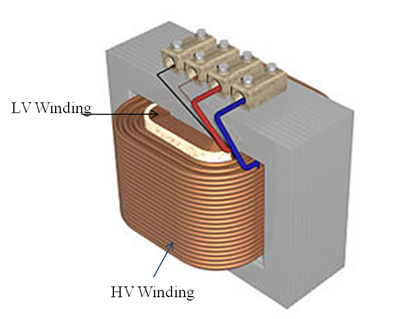
1.The HV winding generally wound over LV winding hence it is easier to access the HV winding turns instead of LV winding.

2.Because of high voltage the current through the HV winding is less compared to LV windings, hence there is less “wear” on the tap changer contacts. Due this low current, in on load tap changer the change over spark will be less.

Transformer Tap changer

Tap changer Primary side:

In this type the tap changer circuit is placed in primary side or supply side. As we know;

Turns ratio = secondary winding turns (Ns)/ primary winding turns (Np).

 Secondary voltage = (supply voltage or primary voltage) / Turns ratio.

By the above formulas it is stated that if the primary turns decreases the turn’s ratio increases hence then secondary voltage decreases. Opposite for the reverse case i.e. primary turns increase leads to turns ratio decrease which increases the secondary voltage.

Figure shows the tap changer on primary winding with tap changing interval of 2.5 % per tap. With this we can understand three conditions:

Transformer Tap changer on Primary Side
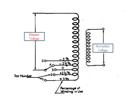
1)In normal operation the tap changer will be at 0% position to provide required designed secondary voltage.

2)If the supply voltage increases or load current decreases there will be an increase in supply voltage which is not desirable. At this case the tap position in the primary winding will rise towards positive direction i.e. +2.5%, and hence decreases the Np. This will increases the turns ratio (Ns/Np) further decreases the secondary voltage.

Consider the load voltage decreased then the tap changer shift towards negative side to increase the primary turns and hence decreases the turn’s ratio. The secondary voltage will increase to compensate the change.

Tap changer Secondary side:

In this the tap changer is placed in secondary side of the transformer. This type of taping is used in step-up transformer where low voltage winding is in primary side and high voltage winding is in secondary side. Figure shows the tap changer circuit on secondary side with tap interval of 2.5 %. In some distribution transformers the tap changer resolution can be up to 1% for fine adjustments.

Transformer Tap changer on secondary Side

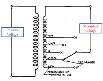
In this the case is reverse compared to primary tap changer. To increase the secondary voltage the tap changer will move towards positive direction and it moves in negative direction to decrease the secondary voltage.

Don't Miss Our Updates
Be the first to get exclusive content straight to your email.
We promise not to spam you. You can unsubscribe at any time.
Invalid email address
You've successfully subscribed !

Continue Reading

Star to Delta and Delta to Star Conversion Formula
Why Armature is placed on Stator for Synchronous machines
AC Motor Speed Control
Electrical Motor Starter Circuits
Faults in a Transformer
Losses of Transformer
Share This Article
Facebook Whatsapp Whatsapp LinkedIn Copy Link
Share
Leave a Comment

Leave a Reply Cancel reply

Your email address will not be published. Required fields are marked *

Stay Connected

128.3kFollowersLike
69.1kFollowersFollow
210kSubscribersSubscribe
38kFollowersFollow

Categories

Explore More

Squirrel Cage Induction Motor vs Slip Ring Induction Motor
Synchronous Motor Working Principle
BLDC Motor Vs AC Induction Motor
What is a Transformer Tap Changer
Synchronous Motor Starting Methods
What is Auto Reclosing?
Difference Between Squirrel Cage and Slip Ring Motors
Types of Transfomer Cooling Methods

Keep Learning

Difference between Induction motor and Synchronous motor

Why rating of Synchronous Generators and Alternators in MVA or KVA

Parallel Operation of Alternators

Types of Generators

Why Starting Current of Induction Motor is High

Distribution transformer

Different Types of Transformers

Classification of valves

Losses in a DC Generator

Advantages of Hydrogen cooling in Synchronous Generators

Learn More

PID Controller

Proportional Integral Derivative Controllers – PID MCQ

Differential Pressure Transmitter Zero Suppression

Basics of DP Transmitter Suppression and Elevation

p-type-semiconductor

N Type and P Type Semiconductors

PLC Program for Automatic Bottle Rejection System

PLC Program for Automatic Bottle Rejection System

Program to implement T Flip Flop logic

T Flip Flop PLC Ladder Diagram

Sensors and Transducers Objective Questions

Top 1000 Instrumentation Engineering Objective Questions

Boiler Protection System

Burner Management System Logic and Interlock

Vortex flow meter Bluff Body

Types of Vortex Flow Meter Sensors

Menu

  • About
  • Privacy Policy
  • Copyright

Quick Links

  • Learn PLC
  • Helping Hand
  • Part Time Job

YouTube Subscribe

Follow US
All rights reserved. Reproduction in whole or in part without written permission is prohibited.
Welcome Back!

Sign in to your account

Username or Email Address
Password

Lost your password?