Design a timer-based sequential PLC program using a single button to activate three outputs and understand the logic behind the concept using the XG-5000 software. This system uses 1 button as a Trigger to activate 3 Outputs, each Output has an Active time limit which is controlled by a Timer and the time parameters of the Timer can be Set. The Trigger button is used to switch program Sequences. When the button is Pressed once, Output-1 will be Active, when the button is Pressed a second time the Output-2 will be Active, and when the button is Pressed a third time the Output-3 will be Active. The system will Stop (not turn off) if the Trigger button is Pressed a fourth time or if the Reset button is Pressed.
Timer-Based Sequential PLC Program
Buttons used:
- The START (P00000) button is used to turn ON the system (standby state).
- The STOP (P00001) button is used to turn OFF the system.
- The TRIGGER_SEQUENCE (P00002) button is used to Start running the system.
- The RESET_SEQUENCE (P00003) button is used to Reset the sequence counter.
System ON/OFF
When the START (P00000) button is Pressed, the memory bit SYSTEM_ON (M00000) in the HIGH state so that the system is in the ON state (Standby).
When the STOP (P00001) button is Pressed, the memory bit SYSTEM_ON (M00000) returns to the LOW state so that the system becomes OFF.
System Run
Before the system is started, the time parameters of the Timer TIMER_MACHINE1 (T0000), TIMER_MACHINE2 (T0001), TIMER_MACHINE3 (T0002) must be Set in the memory word SV_TIMER_MACHINE1 (D00010), SV_TIMER_MACHINE2 (D00011), SV_TIMER_MACHINE3 (D00012).
This program has 3 Sequences which are stored in memory word SEQUENCE (D0).
Sequence-1
When the TRIGGER_SEQUENCE (P00002) button is Pressed once, the value in memory word SEQUENCE (D0) becomes “1” and Output MACHINE_1 (P00040) will be ON. The Output MACHINE_1 (P00040) will be ON and will be OFF when the Timer TIMER_MACHINE1 (T0000) has finished counting.
Sequence-2
When the TRIGGER_SEQUENCE (P00002) button is Pressed a second time, the value in memory word SEQUENCE (D0) increases (+1) to “2” and Output MACHINE_2 (P00041) will be ON. The MACHINE_2 (P00041) Output will be ON and will be OFF when the Timer TIMER_MACHINE2 (T0001) has finished counting.
Sequence-3
When the TRIGGER_SEQUENCE (P00002) button is Pressed a third time, the value in memory word SEQUENCE (D0) increases (+1) to “3” and Output MACHINE_3 (P00043) will be ON. The output MACHINE_3 (P00043) will be ON and will be OFF when the TIMER_MACHINE3 (T0002) Timer has finished counting.
When the RESET_SEQUENCE (P00003) button is Pressed or if the TRIGGER_SEQUENCE (P00002) button is Pressed a fourth time, the memory word SEQUENCE (D0) is Reset to “0” and the system returns to Standby state.
Input & Output Addressing
| Comment | Input (I) | Output (Q) | Memory Bits | Memory Word | Timers |
| START | P00000 | ||||
| STOP | P00001 | ||||
| TRIGGER_SEQUENCE | P00002 | ||||
| RESET_SEQUENCE | P00003 | ||||
| MACHINE_1 | P00040 | ||||
| MACHINE_2 | P00041 | ||||
| MACHINE_3 | P00043 | ||||
| TIMER_MACHINE1 | T0000 | ||||
| TIMER_MACHINE2 | T0001 | ||||
| TIMER_MACHINE3 | T0002 | ||||
| SYSTEM_ON | M00000 | ||||
| SEQUENCE | D00000 | ||||
| SV_TIMER_MACHINE1 | D00010 | ||||
| SV_TIMER_MACHINE2 | D00011 | ||||
| SV_TIMER_MACHINE3 | D00012 |
PLC Programming
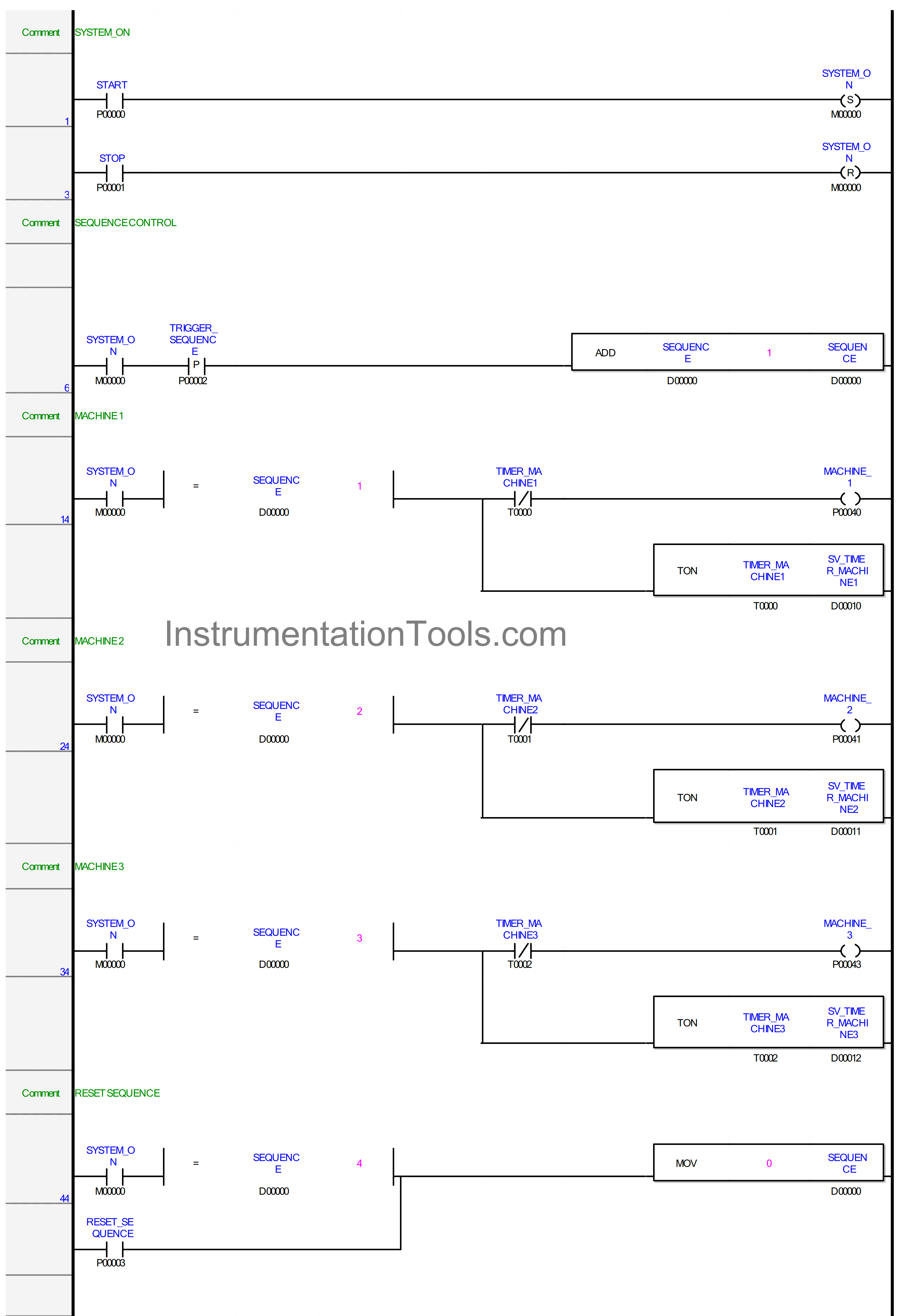
RUNG 1
In this Rung, the memory bit SYSTEM_ON (M00000) changes to the HIGH state if the START (P00000) button is Pressed. Because it uses the SET Coil Instruction, the memory bit SYSTEM_ON (M00000) will remain in the HIGH state even though the START (P00000) button has been Released.
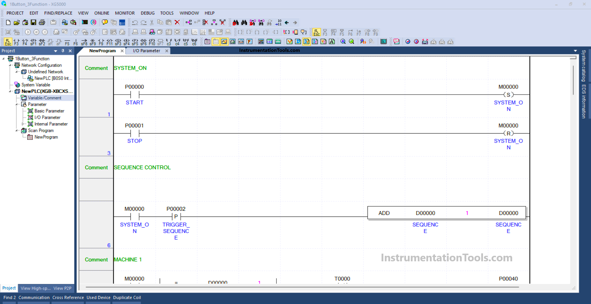
RUNG 3
In this Rung, the memory bit SYSTEM_ON (M00000) will be in LOW state if the STOP (P00001) button is Pressed because it uses the RESET Coil Instruction.
RUNG 6
In this Rung, when the NO contact of memory bit SYSTEM_ON (M00000) in the HIGH state and the TRIGGER_SEQUENCE (P00002) button is Pressed, the value in the memory word SEQUENCE (D00000) will increase (+1). Because the ADD instruction adds a value (+1) to the memory word SEQUENCE (D00000).
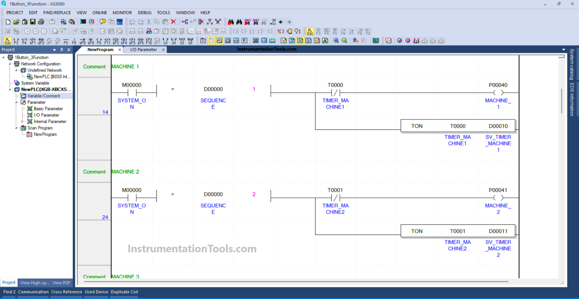
RUNG 14
In this Rung, if the value in memory word SEQUENCE (D00000) is equal to “1”, then the Output MACHINE_1 (P00040) will be ON and the Timer instruction TIMER_MACHINE1 (T0000) will start counting. The timer TIMER_MACHINE1 (T0000) will count according to the “Set value” that has been Set in the memory word SV_TIMER_MACHINE1 (D00010).
When the Timer instruction TIMER_MACHINE1 (T0000) has finished counting, the Output MACHINE_1 (P00040) becomes OFF because of the “Interlock” from TIMER_MACHINE1 (T0000).
RUNG 24
When the value in memory word SEQUENCE (D00000) is equal to “2”, then Output MACHINE_2 (P00041) will be ON and the Timer instruction TIMER_MACHINE2 (T0001) will start counting. The timer TIMER_MACHINE2 (T0001) will count according to the “Set value” that has been Set in the memory word SV_TIMER_MACHINE2 (D00011).
When the Timer instruction TIMER_MACHINE2 (T0001) has finished counting, the Output MACHINE_2 (P00041) becomes OFF because of the “Interlock” from TIMER_MACHINE2 (T0001).
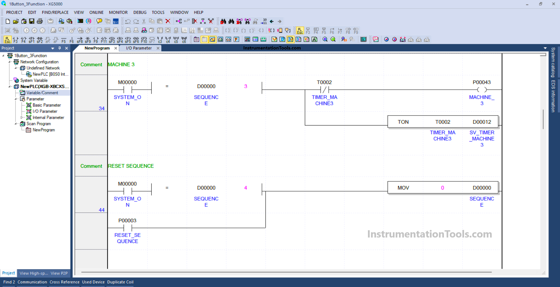
RUNG 34
When the value in the memory word SEQUENCE (D00000) is equal to “3”, the Output MACHINE_3 (P00043) will be ON and the Timer instruction TIMER_MACHINE1 (T0002) will start counting. The TIMER_MACHINE1 (T0002) timer will count according to the “Set value” that has been Set in the memory word SV_TIMER_MACHINE3 (D00012).
When the Timer instruction TIMER_MACHINE3 (T0002) has finished counting, the Output MACHINE_3 (P00043) becomes OFF because of the “Interlock” from TIMER_MACHINE3 (T0002).
RUNG 44
In this Rung, if the NO contact of memory bit SYSTEM_ON (M00000) in the HIGH state and the value in memory word SEQUENCE (D00000) is equal to “4”, then the memory word SEQUENCE (D00000) becomes the value “0”.
Or, when the RESET_SEQUENCE (P00003) button is Pressed, the memory word SEQUENCE (D00000) will becomes the value “0”.
The MOV instruction moves the value “0” to memory word SEQUENCE (D00000).
Read Next:
- What is NOR Flash Memory in PLC?
- Network Switch Port Allocation Details
- PLC Programming for Automatic Gate Control
- Why Baud Rate is Important in Modbus Network?
- PLC Structured Text Program for Marking Machine