This article describes an automatic car washing system controlled via Siemens TIA-Portal. The process runs automatically, including the regulation of water and soap spraying, scrubbing, rinsing, and vehicle drying. All stages of the washing process will be carried out with varying durations. The PLC system is equipped with an alarm indicator that will activate once all stages are completed.
Program Objective
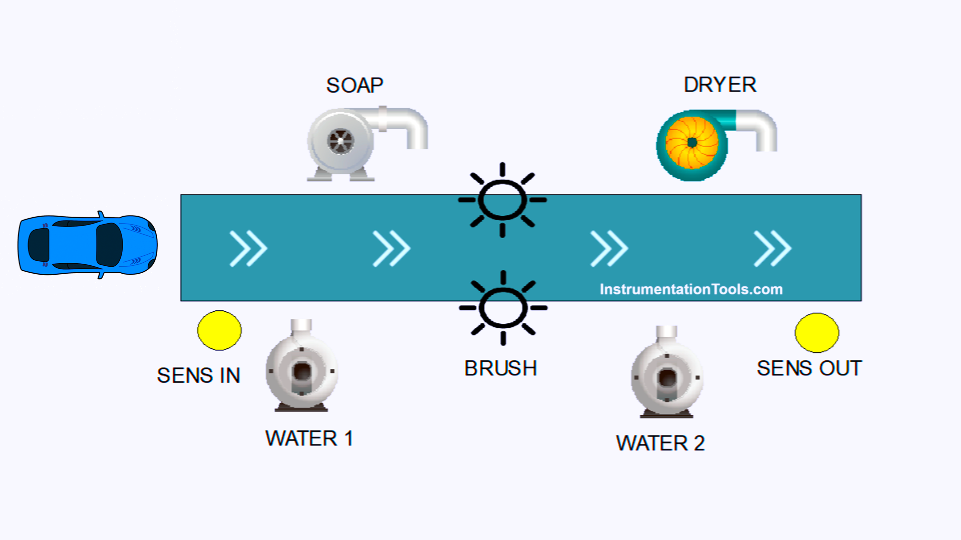
System Steps
Vehicle Detection:
- Sensors detect a car entering the washing area.
- The conveyor moves to carry the car through the washing stages.
Initial Water Spray:
The water pump is activated to evenly wet the car. The water pump will turn on for 6 seconds.
Soap Spray and Cleaning Process:
- The soap pump sprays cleaning fluid over the entire surface of the car. The soap pump will turn on for 5 seconds.
- The brush motor starts rotating to clean the vehicle. The brush motor will turn on for 7 seconds.
Rinsing:
After the cleaning is complete, the water pump turns on again for 4 seconds to clean the remaining soap.
Drying Process:
- After rinsing, the dryer system is activated for 5 seconds to remove remaining water.
- An alarm sounds to indicate that the washing process is complete.
Car Exits the System:
The conveyor stops after the process is finished, allowing the car to exit the washing area.
System Returns to Initial Position:
All devices are deactivated, and the system is ready for the next vehicle.
Mapping Details
| S.No. | Comment | Input (I) | Output (Q) | Memory Bit | Timer |
|---|---|---|---|---|---|
| 1 | PB_START | I0.0 | |||
| 2 | PB_STOP | I0.1 | |||
| 3 | SENS_CAR_IN | I0.2 | |||
| 4 | SENS_CAR_OUT | I0.3 | |||
| 5 | WATER_PUMP1 | Q0.0 | |||
| 6 | SOAP_PUMP | Q0.2 | |||
| 7 | CONVEYOR | Q0.3 | |||
| 8 | MOTOR_BRUSH | Q0.4 | |||
| 9 | DRYER | Q0.5 | |||
| 10 | ALARM | Q0.6 | |||
| 11 | WATER_PUMP2 | Q0.1 | |||
| 12 | TIMER_WATER1 | DB1 | |||
| 13 | TIMER_SOAP | DB2 | |||
| 14 | TIMER_BRUSH | DB3 | |||
| 15 | TIMER_DRYER | DB5 | |||
| 16 | TIMER_WATER2 | DB4 | |||
| 17 | TIMER_ALARM | DB6 | |||
| 18 | SYSTEM_ON | M0.0 | |||
| 19 | IR_TIMER_WATER1 | M0.1 | |||
| 20 | IR_TIMER_WATER2 | M0.2 | |||
| 21 | IR_TIMER_SOAP | M0.3 | |||
| 22 | IR_TIMER_BRUSH | M0.4 | |||
| 23 | IR_TIMER_DRYER | M0.5 | |||
| 24 | IR_TIMER_ALARM | M0.6 | |||
| 25 | IR_SENS_CAR_IN | M0.7 | |||
| 26 | IR_SENS_CAR_OUT | M1.0 |
TIA Portal Car Washing Exercise
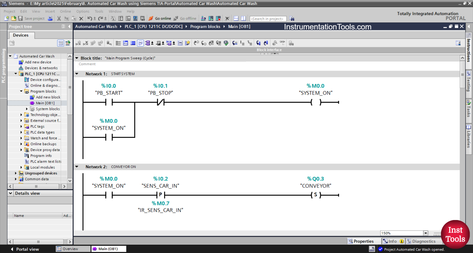
NETWORK 1 (START SYSTEM)
In this network, the memory bit SYSTEM_ON (M0.0) will be in the HIGH state if the PB_START (I0.0) button is pressed. Even though the PB_START (I0.0) button has been released, the memory bit SYSTEM_ON (M0.0) will remain in the HIGH state. Because it uses Latching.
When the PB_STOP (I0.1) button is pressed, the memory bit SYSTEM_ON (M0.0) will be in the LOW state.
NETWORK 2 (CONVEYOR ON)
In this network, the CONVEYOR (Q0.3) output will be ON if the NO contact of the memory bits SYSTEM_ON (M0.0) and the SENS_CAR_IN(I0.2) sensor are in the HIGH state.
Because it uses the SET Output instruction, even though the NO contact of the memory bit SYSTEM_ON (M0.0) or the SENS_CAR_IN (I0.2) sensor is in the LOW state, the CONVEYOR (Q0.3) output state will remain ON.

NETWORK 3 (WATER 1 ON)
In this network, the TIMER_WATER1 (DB1) timer will start counting when the NO contacts of the memory bit SYSTEM_ON (M0.0) and CONVEYOR (Q0.3) are in the HIGH state.
The TIMER_WATER1 (DB1) timer will count up to 6 seconds, and after the timer has finished counting, the memory bit IR_TIMER_WATER1 (M0.1) will be in the HIGH state and the output WATER_PUMP1 (Q0.0) will be ON.
When the NC contact of the memory bit IR_TIMER_SOAP (M0.3) is in the HIGH state, the WATER_PUMP1 (Q0.0) output will be OFF.
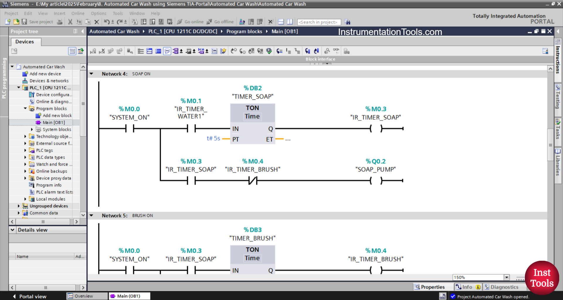
NETWORK 4 (SOAP ON)
In this network, the TIMER_SOAP (DB2) timer will start counting when the NO contacts of the memory bits SYSTEM_ON (M0.0) and IR_TIMER_WATER1 (M0.1) are in the HIGH state.
The TIMER_SOAP (DB2) timer will count up to 5 seconds, and after the TIMER_SOAP (DB2) timer has finished counting, the memory bit IR_TIMER_SOAP (M0.3) will be in the HIGH state and the SOAP_PUMP(Q0.2) output will be ON.
When the NC contact of the memory bit IR_TIMER_BRUSH (M0.4) is in the HIGH state, the SOAP_PUMP (Q0.2) output will be OFF.

NETWORK 5 (BRUSH ON)
In this network, the TIMER_BRUSH (DB3) timer will start counting when the NO contacts of the memory bits SYSTEM_ON (M0.0) and IR_TIMER_SOAP(M0.3) are in the HIGH state.
The TIMER_BRUSH (DB3) timer will count up to 7 seconds, and after the timer has finished counting, the memory bit IR_TIMER_BRUSH (M0.4) will be in the HIGH state and the MOTOR_BRUSH (Q0.4) output will be ON.
When the NC contact of the memory bit IR_TIMER_WATER2 (M0.2) is in the HIGH state, the MOTOR_BRUSH (Q0.4) output will be OFF.
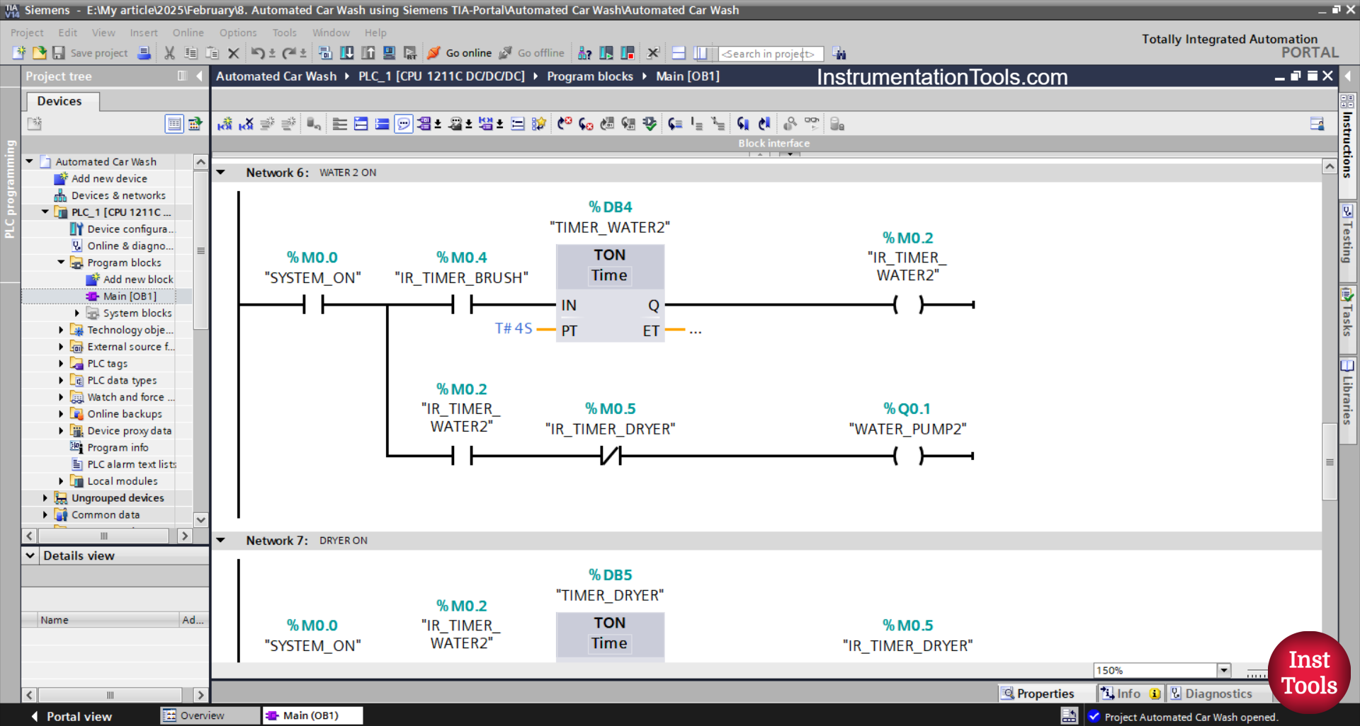
NETWORK 6 (WATER 2 ON)
In this network, the TIMER_WATER2 (DB4) timer will start counting if the NO contacts of the memory bits SYSTEM_ON (M0.0) and IR_TIMER_BRUSH (M0.4) are in the HIGH state.
The TIMER_WATER2 (DB4) timer will count up to 4 seconds, and after the timer has finished counting, the memory bit IR_TIMER_WATER2 (M0.2) will be in the HIGH state and the WATER_PUMP2 (Q0.1) output will be ON.
When the NC contact of the memory bit IR_TIMER_DRYER (M0.5) is in the HIGH state, the output WATER_PUMP2 (Q0.1) will be OFF.
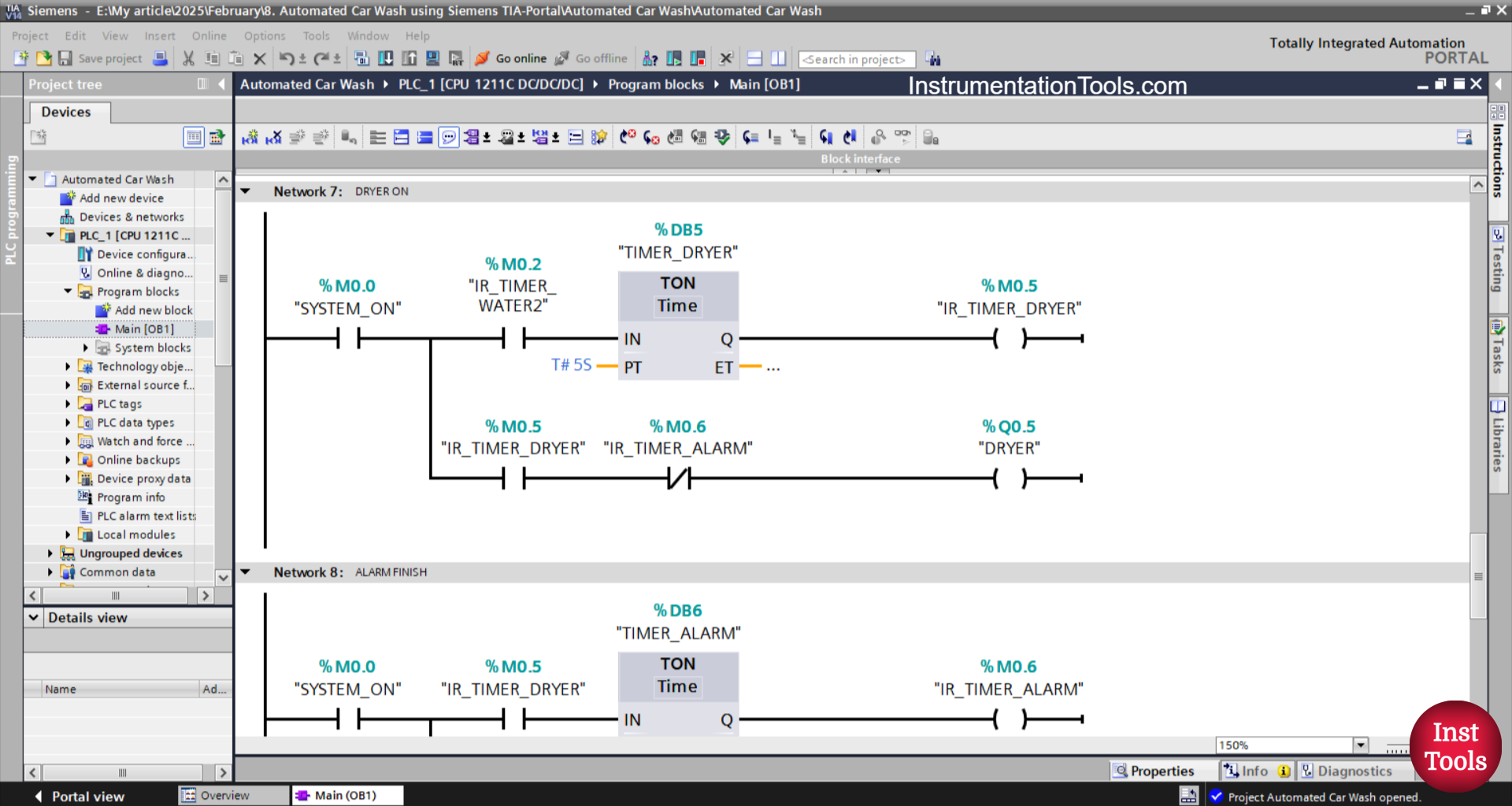
NETWORK 7 (DRYER ON)
The TIMER_DRYER (DB5) timer will start counting if the NO contacts of the memory bits SYSTEM_ON (M0.0) and IR_TIMER_WATER2 (M0.2) are in the HIGH state.
The TIMER_DRYER (DB5) timer will count up to 5 seconds, and after the timer has finished counting, the memory bit IR_TIMER_DRYER (M0.5) will be in the HIGH state and the output WATER_PUMP2 (Q0.1) will be ON.
When the NC contact of the memory bit IR_TIMER_ALARM (M0.6) is in the HIGH state, the DRYER (Q0.5) output will be OFF.
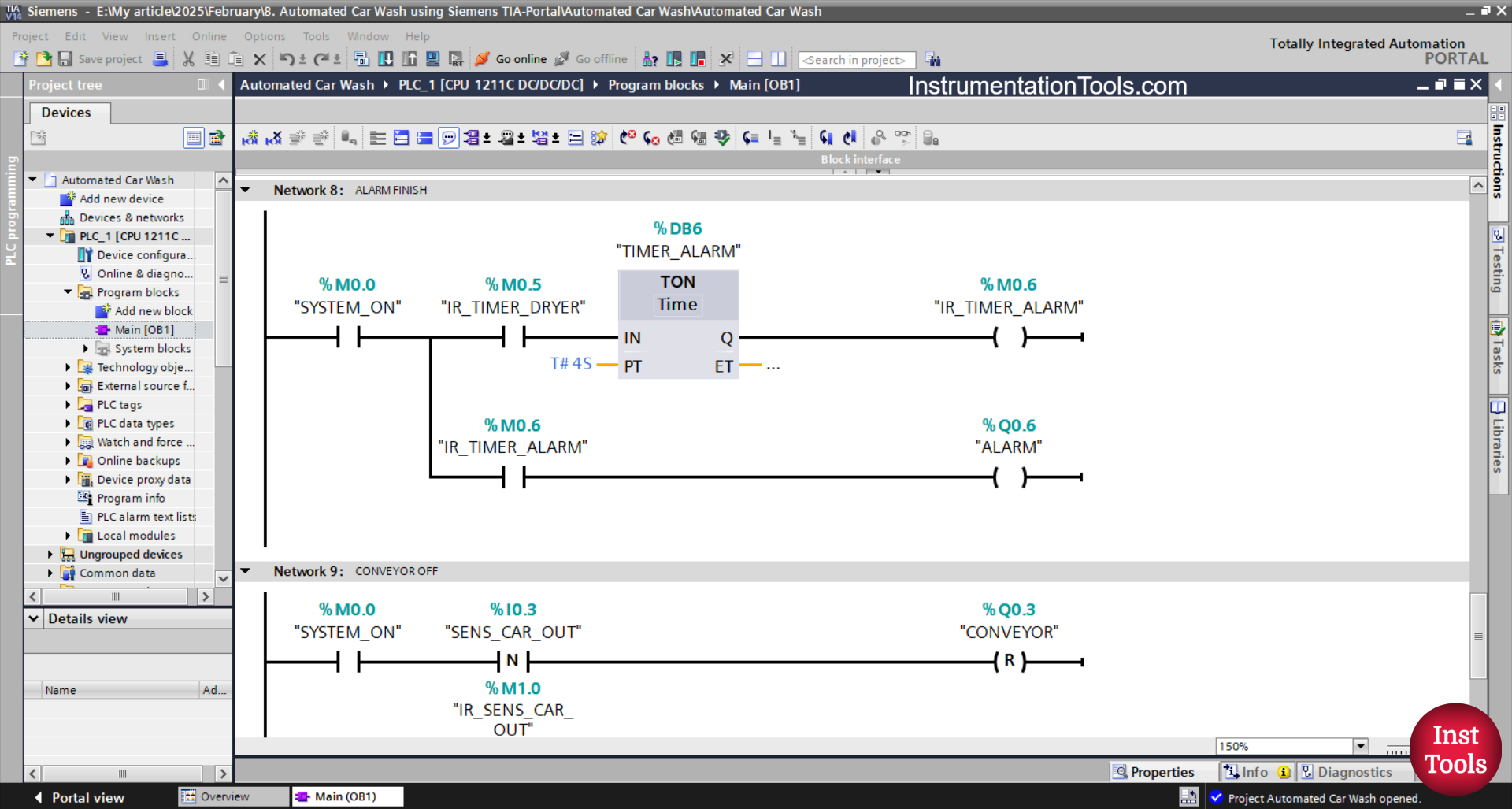
NETWORK 8 (FINISH ALARM)
The TIMER_ALARM (DB6) timer will start counting up to 4 seconds when the NO contacts of the memory bits SYSTEM_ON (M0.0) and IR_TIMER_DRYER (M0.5) are in the HIGH state.
After the TIMER_ALARM (DB6) timer has finished counting, the memory bit IR_TIMER_ALARM (M0.6) will be in the HIGH state and the ALARM (Q0.6) output will be ON.
NETWORK 9 (CONVEYOR OFF)
In this network, the CONVEYOR (Q0.3) output will be OFF when the NO contact of the memory bits SYSTEM_ON (M0.0) and the SENS_CAR_OUT (I0.3) sensor are in the HIGH state.
Read Next: